
Radial or diagonal ventilator wheel

A fan impeller, oblique flow technology, applied in the field of radial or oblique flow fan impellers, can solve the problems of aerodynamic loss, efficiency loss, air flow separation, etc., achieve efficiency and noise emission improvement, reduce interaction, save effect of material

Active Publication Date: 2013-05-01
EBM PAPST MULFINGEN GMBH & CO KG
View PDF4 Cites 0 Cited by
  • Summary
  • Abstract
  • Description
  • Claims
  • Application Information

AI Technical Summary

Problems solved by technology

This may cause separation of airflow, or even reverse flow, resulting in loss of aerodynamics, loss of efficiency, and increased noise emission

Method used


Image

  • Radial or diagonal ventilator wheel
  • Radial or diagonal ventilator wheel
  • Radial or diagonal ventilator wheel

Examples


Embodiment Construction

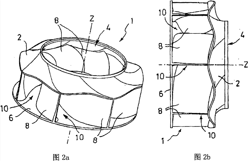
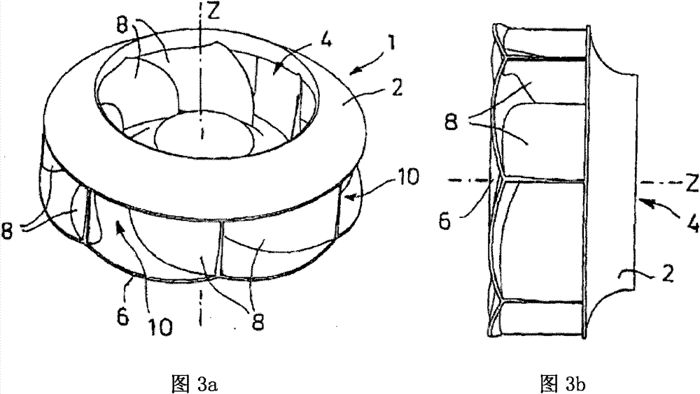
[0021] In all embodiments, according to the invention, the fan impeller 1 to be driven in rotation about the axis of rotation Z comprises a cover plate 2, a base plate 6 opposite in the axial direction Z, and a plurality of fan blades 8, so that The cover plate 2 has an air inlet opening 4, which is preferably arranged substantially centrally, for the intake air. The fan blade 8 is installed between the bottom sheet 6 and the cover sheet 2; or, the fan blade 8 is completely or partially formed by molding the bottom sheet 6 and / or the cover sheet 2 (with Figure 8 Compare), at this time, the disks 2, 6 are directly connected to each other in these areas. The fan blades 8 are arranged in a certain circumferential distribution around the axis of rotation Z and the air inlet 4 . An inter-blade flow channel 10 is formed between every two adjacent fan blades 8 in the circumferential direction, and the inter-blade flow channel 10 conducts radially or laterally outwardly from the are...


PUM


Abstract

The fan wheel (1) has a shroud (2) with an inlet port (4), a baseplate (6) and several fan blades (8) that are arranged over the circumference of the inlet port and around an axis of rotation (Z). The shroud and baseplate comprise a non-rotationally symmetrical geometry having a continuous and point-invariable profile with respect to the axis of rotation, along the axial or axially parallel direction.

Description

technical field [0001] The invention relates to a fan impeller implemented as a radial fan or a diagonal fan (Diagonal ventilator), said fan impeller comprising a cover sheet with an air inlet, a bottom sheet and a plurality of Fan blades distributed around the rotation axis, wherein the cover sheet and / or the bottom sheet have a non-rotationally symmetrical geometric structure. [0002] In this relation, the term "non-rotational symmetry" refers to two arbitrarily different radial sections of the base and / or cover in two planes containing the axis of rotation and containing the difference angle in the circumferential direction, in In the case of different circumferential angles, they do not overlap, but deviate from each other. The deviation can essentially exist in the direction of the axis of rotation (axial) and / or in the radial direction (radial). In other words, this means that in the case of non-rotational symmetry, the object will not coincide with itself after turni...

Claims


Application Information

Patent Timeline
Patent Type & Authority Patents(China)
IPC IPC(8): F04D29/26
CPCF04D29/281F04D29/681F04D29/162
Inventor 卡特琳·博尔马克·施奈德于尔根·朔内
Owner EBM PAPST MULFINGEN GMBH & CO KG
Learn More