
Method for construction of bridge cast-in-situ pre-stressed concrete continuous beam

A construction method and concrete technology, applied in bridges, bridge materials, bridge construction, etc., can solve the problems of heavy foundation reinforcement workload, uneconomical, and inability to meet construction period requirements, and achieve construction cost saving, wide application range, and material recycling high rate effect

Active Publication Date: 2010-09-08
CHINA RAILWAY NO 3 GRP CO LTD +1
View PDF4 Cites 21 Cited by
  • Summary
  • Abstract
  • Description
  • Claims
  • Application Information

AI Technical Summary

Problems solved by technology

[0003] The invention aims to solve the problems that the existing hanging basket hanging irrigation construction cannot meet the construction period requirements, the cast-in-place construction of the full hall support has strict requirements on the bearing capacity of the foundation and the working space, and the foundation reinforcement workload is large and uneconomical during the cast-in-place construction of the pier type support. , providing a construction method for cast-in-place prestressed concrete continuous beams at bridge sites that can achieve safe and rapid construction, save engineering costs and have a wide range of applications

Method used


Image

  • Method for construction of bridge cast-in-situ pre-stressed concrete continuous beam
  • Method for construction of bridge cast-in-situ pre-stressed concrete continuous beam
  • Method for construction of bridge cast-in-situ pre-stressed concrete continuous beam

Examples


Embodiment Construction

[0026] The specific embodiment of the present invention will be further described in conjunction with the accompanying drawings.

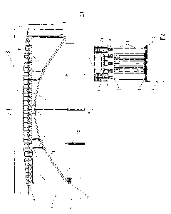
[0027] The construction method of the cast-in-place prestressed concrete continuous beam at the bridge site: build the tie-bar arch support at the lower part of the prestressed concrete continuous beam body, and set the vertical support structure under the end position of the concrete continuous beam body, and then install the tie-bar arch Set columns, beams, longitudinal beams and horizontal distribution beams between the bracket and the concrete continuous beam in sequence from bottom to top, and finally, according to the design line shape of the continuous concrete continuous beam, build the formwork system for the cast-in-place beam on the horizontal distribution beam , finish the construction of prestressed concrete continuous beam at last; Described tie-rod arch bracket comprises arch and the tie-rod connecting the two ends of the arch, the ju...


PUM


Abstract

The invention belongs to the technical field of bridge engineering construction, particularly relates to a method for the construction of a bridge cast-in-situ pre-stressed concrete continuous beam, which solves the problems that the existing construction method is incapable of meeting the requirements for construction period, imposes strict requirements for the bearing capacity and operation space of a foundation, and has high-workload and uneconomic foundation reinforcement. The method comprises the following steps: building a tied-arch support below the position where the concrete continuous beam is arranged; arranging a vertical supporting structure below the position of the tip of the concrete continuous beam; then, building a formwork system above the tied-arch support; and sequentially constructing the beam 'from middle to two sides', and reserving closure segments at two sides of the beam, wherein the tied-arch support comprises an arch part and a tie bar connected in a hinged way, and a support is arranged at the bottom of the tie bar. Accordingly, the invention has the following beneficial effects: the method which is not restricted by the construction environment and conditions can reduce the construction period, save the construction cost, meet the requirements for cast-in-situ construction and prevent the existing structure from being damaged by the stress system; and the method has the advantages of wide applicable range, high material recovery rate and obvious economic benefit.

Description

technical field [0001] The invention belongs to the technical field of bridge engineering construction, and in particular relates to a construction method of cast-in-place prestressed concrete continuous beams at bridge positions. Background technique [0002] For the construction of prestressed concrete continuous girder bridge body, according to different types of support, there are five commonly used construction methods: 1. Hanging basket cantilever pouring construction method: using segmental cantilever operation, no need to erect supports throughout the length, with It has the advantages of light structure, simple and convenient assembly, and wide application range. For the construction of concrete continuous beams with a span greater than 100m, it has obvious advantages in terms of safety, energy saving, and construction period; The types of scaffolding include bowl buckle type and fastener type. This method has a high material turnover rate, flexible support structur...

Claims


Application Information

Patent Timeline
IPC IPC(8): E01D21/00E04G13/04E01D101/24E01D101/28
Inventor 张宇宁胡国伟张俊兵
Owner CHINA RAILWAY NO 3 GRP CO LTD
Learn More