
Method for positioning transverse cracks of carbon fiber composite material by using chirp grating

A composite material and chirped grating technology, applied in the field of material science, can solve problems such as high cost, complex equipment, and difficult online monitoring, and achieve the effect of simple method and low cost

Inactive Publication Date: 2010-09-01
SHENYANG INST OF AERONAUTICAL ENG
View PDF0 Cites 2 Cited by
  • Summary
  • Abstract
  • Description
  • Claims
  • Application Information

AI Technical Summary

Problems solved by technology

Traditional non-destructive monitoring methods for composite materials are expensive, complex equipment and difficult to achieve online monitoring

Method used


Image

  • Method for positioning transverse cracks of carbon fiber composite material by using chirp grating
  • Method for positioning transverse cracks of carbon fiber composite material by using chirp grating
  • Method for positioning transverse cracks of carbon fiber composite material by using chirp grating

Examples


Embodiment Construction

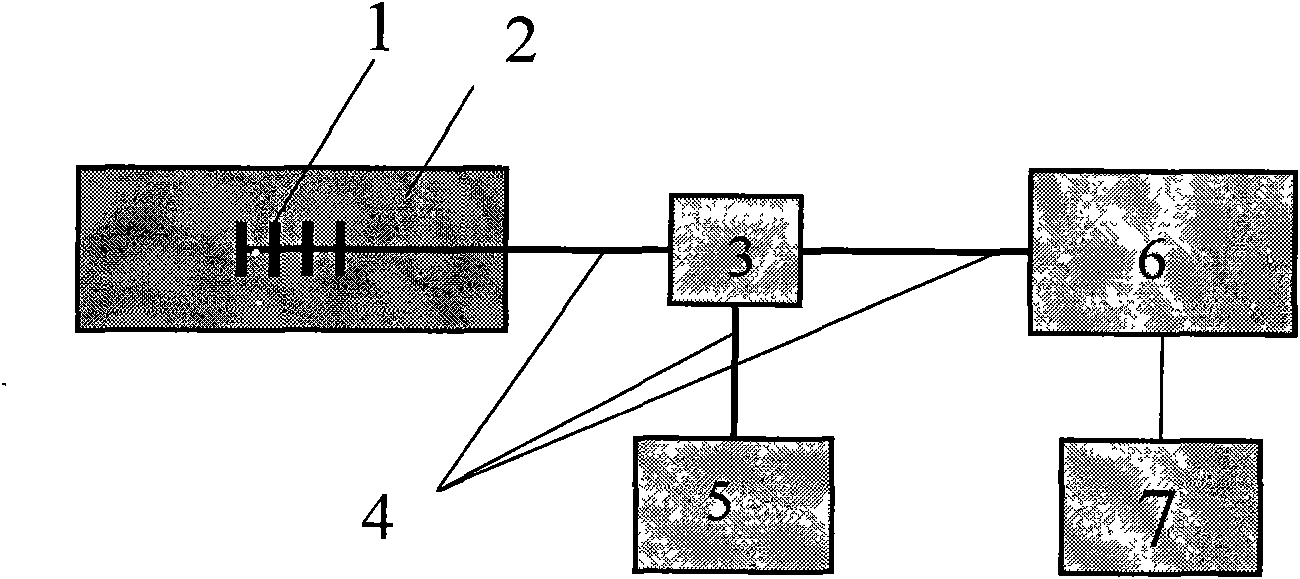
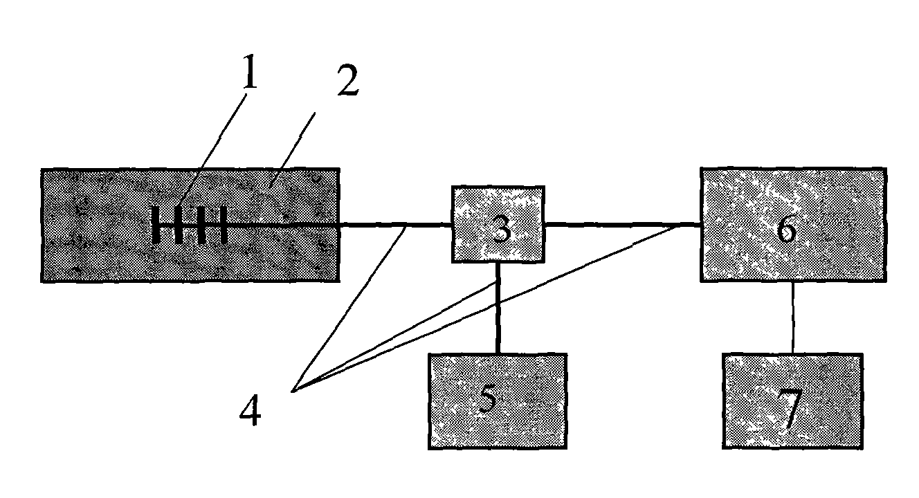
[0013] exist figure 1 Among them, symbol 1 represents chirped grating sensor; symbol 2 represents composite orthogonal laminate; symbol 3 represents coupler; symbol 4 represents optical fiber; symbol 5 represents broadband light source; symbol 6 represents optical fiber sensor analyzer; symbol 7 represents computer analysis system.

[0014] Such as figure 1 Shown: A method for locating transverse cracks in carbon fiber composites with chirped gratings, the steps are as follows:

[0015] (1) Make carbon fiber composite material orthogonal laminate 2, and its layering sequence is [0° 2 / 90° 4 / 0° 2 ], the chirped grating sensor 1 is embedded in the 0° layer of the carbon fiber composite orthogonal laminate 2, adjacent to the 90° layer.

[0016] (2) The chirped grating sensor 1 is connected to the coupler 3 through the optical fiber 4, and then the coupler 3 is connected to the broadband light source 5 through the optical fiber 4, and the coupler 3 is connected to the fiber ...


PUM


Abstract

The invention discloses a method for positioning transverse cracks of a carbon fiber composite material by using a chirp grating, which comprises the following steps of: (1) manufacturing a carbon fiber composite material cross-ply laminate with the stacking sequence of [0-degree 2 / 90-degree 4 / 0-degree 2], and embedding a chirp grating sensor into a 0-degree layer the carbon fiber composite material cross-ply laminate, wherein the chirp grating sensor is adjacent to a 90-degree layer; (2) under a condition with a constant temperature, using an optical fiber sensing analyzer to monitor a chirp grating reflection spectrum of a carbon fiber composite material test piece in a quasistatic tensile test; and (3) adjusting the length of the chirp grating to be accordant with a bandwidth phase of the chirp grating reflection spectrum before embedding in a coordinate system to ensure that a wavelength position corresponding to a point with decreased light intensity and a grating position corresponding to the wavelength in the chirp grating reflection spectrum are the positions where the transverse cracks are generated in the 90-degre layer of the composite material at that time. The method is simple, has a low cost, and can detect the transverse cracks in the carbon fiber composite material in real time.

Description

technical field [0001] The invention relates to a non-destructive testing method, in particular to a method for locating transverse cracks in carbon fiber composite materials by using a chirped grating, and belongs to the field of material science. Background technique [0002] Carbon fiber composites are prone to various forms of damage such as cracks, fiber breakage, and delamination during service. Among them, transverse cracks in non-axial layers are the most likely damage mode. When the transverse crack density increases to a certain extent, it will induce The generation of other damage modes such as delamination eventually leads to structural failure. In order to ensure the safety of the structure, an effective structural health monitoring technology is needed, so that the crack generation and expansion of the composite structure can be monitored in real time before the accumulation of cracks reaches the threat to the structural safety, so as to ensure its safe operati...

Claims


Application Information

Patent Timeline
IPC IPC(8): G01N21/88G01N21/55
Inventor 卢少微王柏臣陈平
Owner SHENYANG INST OF AERONAUTICAL ENG
Learn More