Multi-antenna transmit diversity method and device

A transmit diversity, multi-antenna technology, applied in space transmit diversity, diversity/multi-antenna systems, and error prevention/detection through diversity reception, can solve the problem of not providing a multi-antenna transmit diversity scheme, and achieve good diversity gain. Effect

Inactive Publication Date: 2014-03-12
ZTE CORP
View PDF4 Cites 0 Cited by
  • Summary
  • Abstract
  • Description
  • Claims
  • Application Information

AI Technical Summary

Problems solved by technology

[0005] In view of this, the main purpose of the present invention is to provide a multi-antenna transmit diversity method and device to solve the problem that the current related art does not provide a multi-antenna transmit diversity scheme

Method used


Image

  • Multi-antenna transmit diversity method and device
  • Multi-antenna transmit diversity method and device
  • Multi-antenna transmit diversity method and device

Examples


example 1

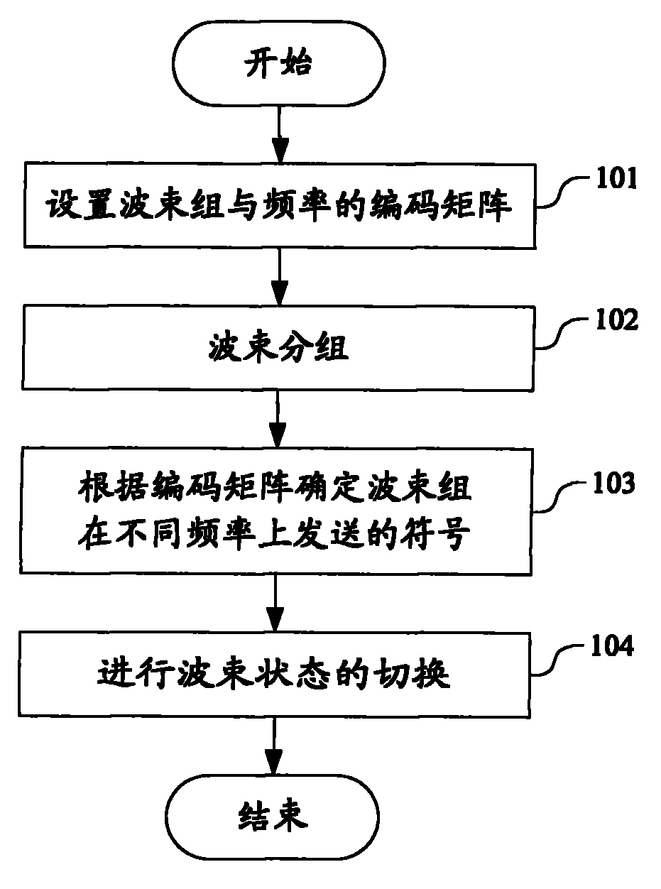
[0041] Example 1, see figure 1 , the specific process includes the following steps:

[0042] Step 101A: For the 8-antenna 3GPP Long Term Evolution Advanced Communication System, set the coding matrix of the beam group and the frequency as: The diversity mode of the coding matrix is ​​space-frequency block coding. Among them, each row of the encoding matrix corresponds to a different frequency, and each column corresponds to a different beam group, x 1 、x 2 is the symbol before encoding, x * Indicates the conjugate of x.

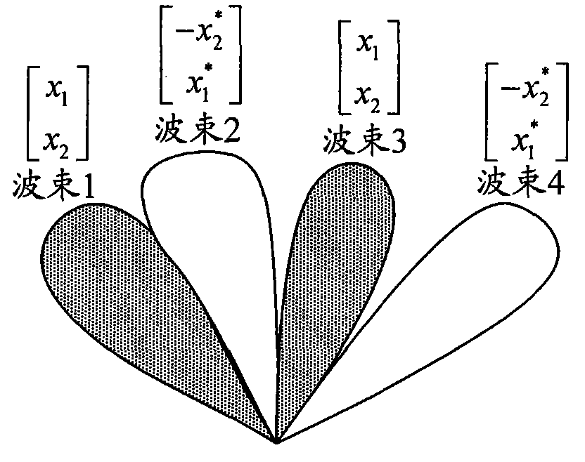
[0043] Step 102A: The cell is sequentially divided into four beams: beam 1, beam 2, beam 3, and beam 4 according to the angle of antenna coverage. Beam 1 is a beam generated by the weight value of the antenna preset by the base station; Beam 4 is an adaptive beam. Assume that the specified spatial area covered by the base station is 0° to 120°, beam 1 is aligned at 15°, beam 2 is aligned at 45°, beam 3 is aligned at 75°, and beam 4 is aligned at 105°. ...

example 2

[0046] Instance two, see figure 1 , the specific process includes the following steps:

[0047] Step 101B: For the 8-antenna 3GPP Long Term Evolution Advanced Communication System, set the coding matrix of beam groups and frequencies as: The diversity mode of the coding matrix is ​​space-frequency block coding. Among them, each row of the encoding matrix corresponds to a different frequency, and each column corresponds to a different beam, x 1 、x 2 is the symbol before encoding, x * Indicates the conjugate of x.

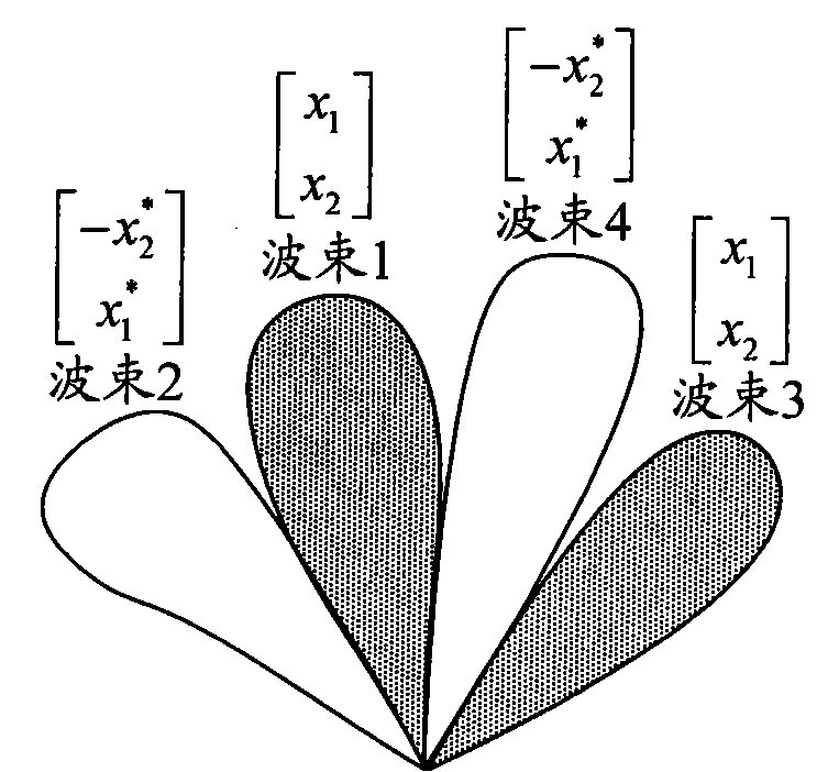
[0048] Step 102B: Each cell is divided into beam 1 and beam 2. Both beam 1 and beam 2 are adaptive beams generated according to the angle of arrival information of the terminal. The shape of the beam is as follows Figure 3A shown. Beam 1 corresponds to beam group 1, and beam 2 corresponds to beam group 2, wherein beam 1 corresponds to the direction of the angle of arrival with the largest energy, and beam 2 corresponds to the direction of the angle of arrival...


PUM


Abstract

The invention discloses a multi-antenna transmit diversity method and a device. In the scheme of the invention, the method comprises the following steps: setting a coding matrix of wave beam groups and frequencies; dividing wave beams generated by a plurality of antennas into two misaligned groups to obtain two wave beam groups; and determining signs sent by the wave beam groups at different frequencies according to the coding matrix. The invention provides a multi-antenna transmit diversity scheme, and solves the problem that the current relevant technology does not provide the multi-antenna transmit diversity scheme, in addition, good diversity grain can be obtained at the same time of not increasing the additional pilot frequency overhead. The invention has the technical scheme that the multi-antenna transmit diversity is combined with the wave beam formation in a multi-antenna communication system, different signs correspond to different wave beam groups, and further, the state switching of the wave beam group is carried out. Thereby, compared with the traditional two-antenna space-frequency coding, the diversity scheme of the invention has the performance grain of 6dB, and in addition, the signs can be completely covered in the state switching of the wave beam groups.

Description

technical field [0001] The invention relates to the field of wireless communication, in particular to a multi-antenna transmit diversity method and device. Background technique [0002] In the 3rd Generation Partnership Project (3GPP, 3rd Generation Partnership Project) Long-Term Evolution (LTE, Long-Term Evolution) system, the downlink defines that the diversity mode when the transmit antenna is 2 antennas is Space Frequency Block Coding (SFBC, Space Frequency Block Codes,), the encoding matrix is: Among them, each row of the encoding matrix corresponds to a different frequency, and each column corresponds to a different antenna, x 1 、x 2 Symbol before space-frequency coding, x * Indicates the conjugate of x. [0003] The downlink also defines the diversity mode when there are 4 antennas as frequency switching diversity (SFBC+FSTD, SFBC+Frequency Switch Time Division), and the encoding matrix is: Each row of the encoding matrix corresponds to a different frequency, a...

Claims


Application Information

Patent Timeline
Patent Type & Authority Patents(China)
IPC IPC(8): H04B7/06H04B7/08H04L1/06
Inventor 王衍文李岩谭欢喜
Owner ZTE CORP
Why Eureka
Try Eureka