
PWM rectifier

A rectifier and PWM signal technology, applied in the direction of converting AC power input to DC power output, high-efficiency power electronic conversion, output power conversion device, etc., can solve the problems of worsening response of the control system and longer feedback sampling period

Active Publication Date: 2010-08-25
FANUC LTD
View PDF6 Cites 11 Cited by
  • Summary
  • Abstract
  • Description
  • Claims
  • Application Information

AI Technical Summary

Problems solved by technology

[0005] However, in the conventional method, there is a side effect that the responsiveness of the control system deteriorates because the sampling period of the feedback becomes longer with the reduction of the PWM frequency.

Method used


Image

  • PWM rectifier
  • PWM rectifier
  • PWM rectifier

Examples


Embodiment Construction

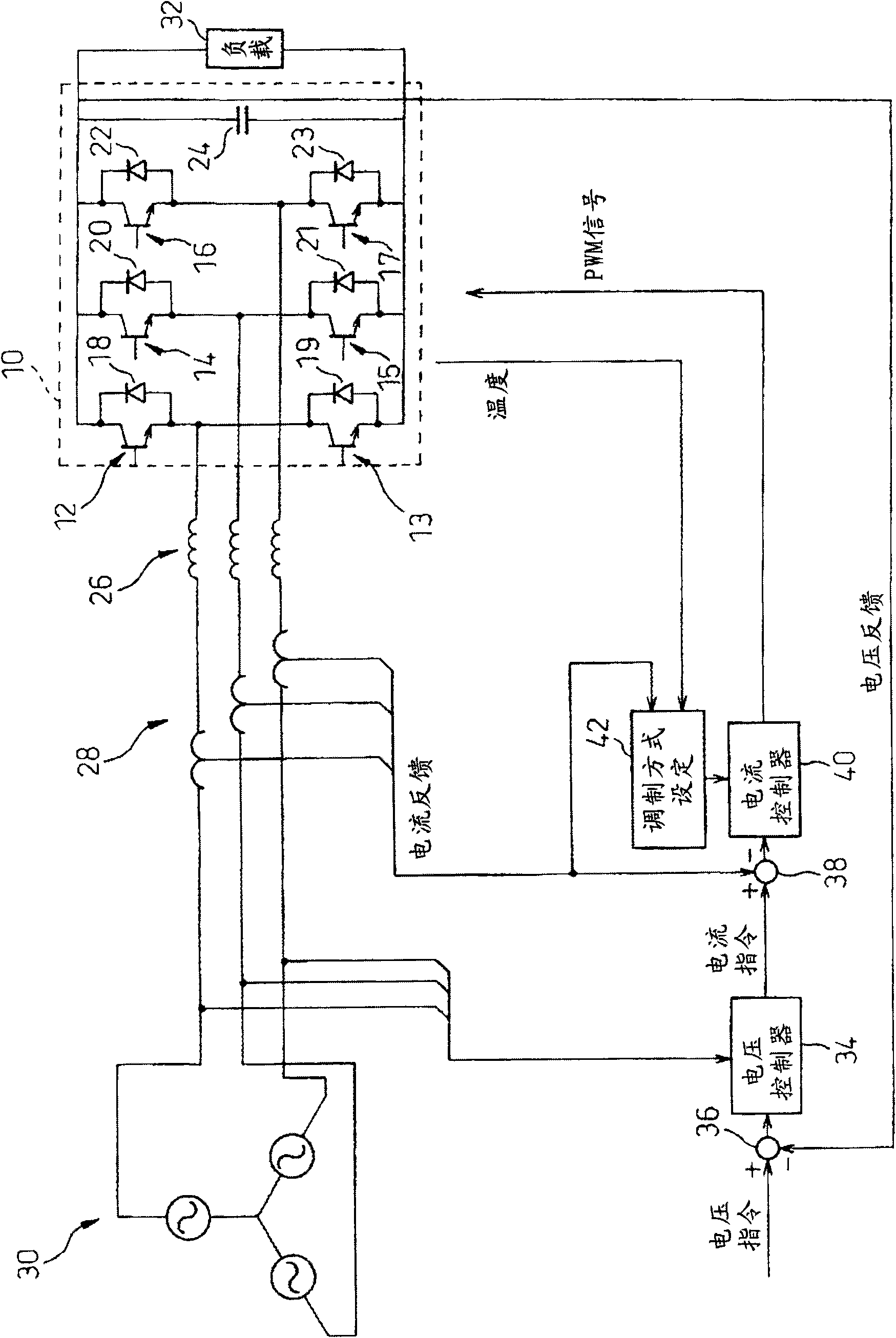
[0019] FIG. 1 is a block diagram showing the configuration of a PWM rectifier according to an embodiment of the present invention.

[0020] The main circuit unit 10 of this PWM rectifier is composed of transistors 12 to 17 , diodes 18 to 23 , and a smoothing capacitor 24 connected as shown in the figure. A three-phase AC power supply 30 is connected to the input side of the main circuit unit 10 via an AC reactor 26 and a converter 28 , and a load 32 such as a PWM inverter is connected to the output side.

[0021] The adder 36 outputs the deviation (voltage deviation) of the output voltage of the PWM rectifier, that is, the voltage of the filter capacitor 24 from the voltage command. The voltage controller 34 outputs a current command as a signal synchronized with the three-phase AC power supply and having an amplitude proportional to the voltage deviation, based on the voltage deviation output from the adder 36 and the voltage of the three-phase AC power supply 30 . The adder...


PUM


Abstract

Disclosed is a PWM rectifier in which switching losses in a semiconductor device are reduced without degrading the response of a control system. In a PWM over modulation region, the modulation scheme is set to a three-phase modulation scheme. In other regions, a switchover condition such as the amplitude of an input current is acquired and compared with a switchover level. If the switchover condition equals or exceeds the switchover level, the modulation scheme is switched over to a modified two-phase modulation scheme which reduces the number of switching operations to two thirds for the same PWM frequency.

Description

technical field [0001] The present invention relates to a PWM rectifier for converting three-phase alternating current into direct current by means of switching controlled semiconductor elements with PWM (pulse width modulation) signals. Background technique [0002] A direct converter (converter: rectifier) ​​that converts industrial power into DC power and supplies power to an inverter (inverter) that drives a motor is used in motor control devices that drive machine tools, industrial machines, and robots. . [0003] In recent years, rectifiers using pulse width modulation (PWM) have been increasingly used in response to the need to reduce high-order harmonics and reactive power in power supplies. Since high-speed switching of semiconductor elements is performed in this PWM rectifier, switching losses occur. Therefore, compared with the conventional diode rectification type rectifier, there are problems that the loss of the power conversion device increases and the volum...

Claims


Application Information

Patent Timeline
Patent Type & Authority Applications(China)
IPC IPC(8): H02M7/217
CPCH02M7/219H02M2001/0048Y02B70/1491H02M1/0048Y02B70/10
Inventor 岩下平辅置田肇丹羽正一山本健太
Owner FANUC LTD
Learn More