
Weather-proof micro-trigger controlled silicon and manufacturing method thereof

A manufacturing method and micro-triggering technology, which are applied in semiconductor/solid-state device manufacturing, electrical components, thyristors, etc., can solve the problems of increased cost, large on-state voltage drop, and thyristor is susceptible to interference, and achieves improved ignition energy, The effect of faster switching

Inactive Publication Date: 2010-08-25
厦门泰格微电子科技有限公司
View PDF1 Cites 3 Cited by
  • Summary
  • Abstract
  • Description
  • Claims
  • Application Information

AI Technical Summary

Problems solved by technology

However, the trigger current of the micro-triggered unidirectional thyristor in the prior art will change drastically with the change of temperature: the trigger current becomes larger at low temperature, and the trigger current at -40°C is 6 to 8 times that of normal temperature 25°C. It makes it difficult for the thyristor to be triggered and turned on; and the trigger current becomes smaller at high temperature, and the trigger current at 80°C is 0.1 to 0.2 times that at room temperature of 25°C, which makes the thyristor susceptible to interference and misconduct
Therefore, it cannot meet the environmental requirements of high and low temperature changes.
[0005] Secondly, in the production process of existing thyristor products, the trigger current has a large dispersion, and the I GT When controlling 30-60μA, the process is very difficult, the yield is low and the cost increases
[0006] In addition, the low switching speed and large on-state voltage drop of the micro-triggered unidirectional thyristor in the prior art also limit the product application

Method used


Image

  • Weather-proof micro-trigger controlled silicon and manufacturing method thereof
  • Weather-proof micro-trigger controlled silicon and manufacturing method thereof
  • Weather-proof micro-trigger controlled silicon and manufacturing method thereof

Examples


Embodiment Construction

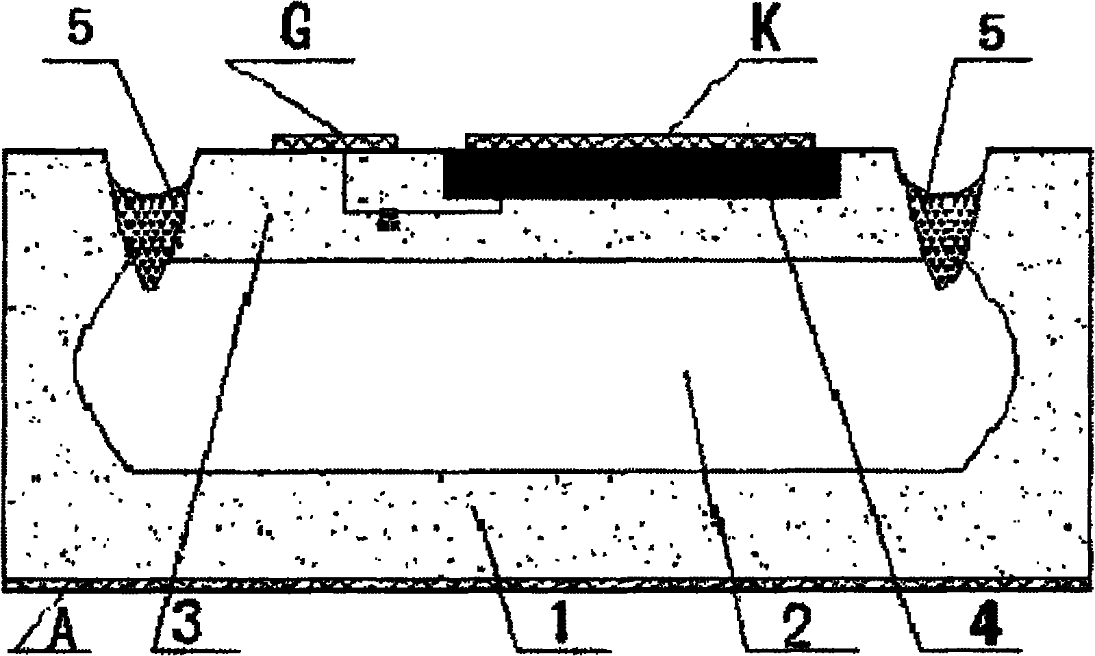
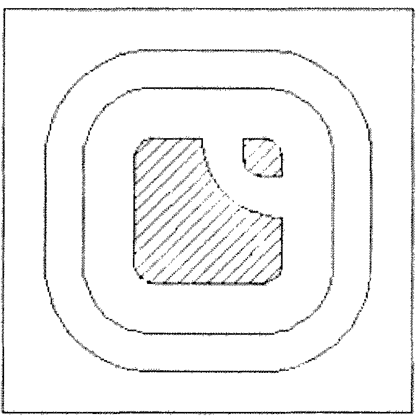
[0031] Please refer to Fig. 4, Fig. 5 and Fig. 6 together. The embodiment of the weather-resistant micro-trigger thyristor of the present invention is a PNP structure, and the PNP structure includes a P-type anode region 1, an N-type long base region 2, and a P-type Short base region 3.

[0032] One side of the PNP structure is P-type silicon, that is, the short base region 3 is provided with N + emitter region 4 and gate electrode G, the N + A cathode electrode K is arranged on the emitter region 4 .

[0033] An anode electrode A is provided on the P-type silicon on the other side of the PNP structure, that is, the anode region 1 .

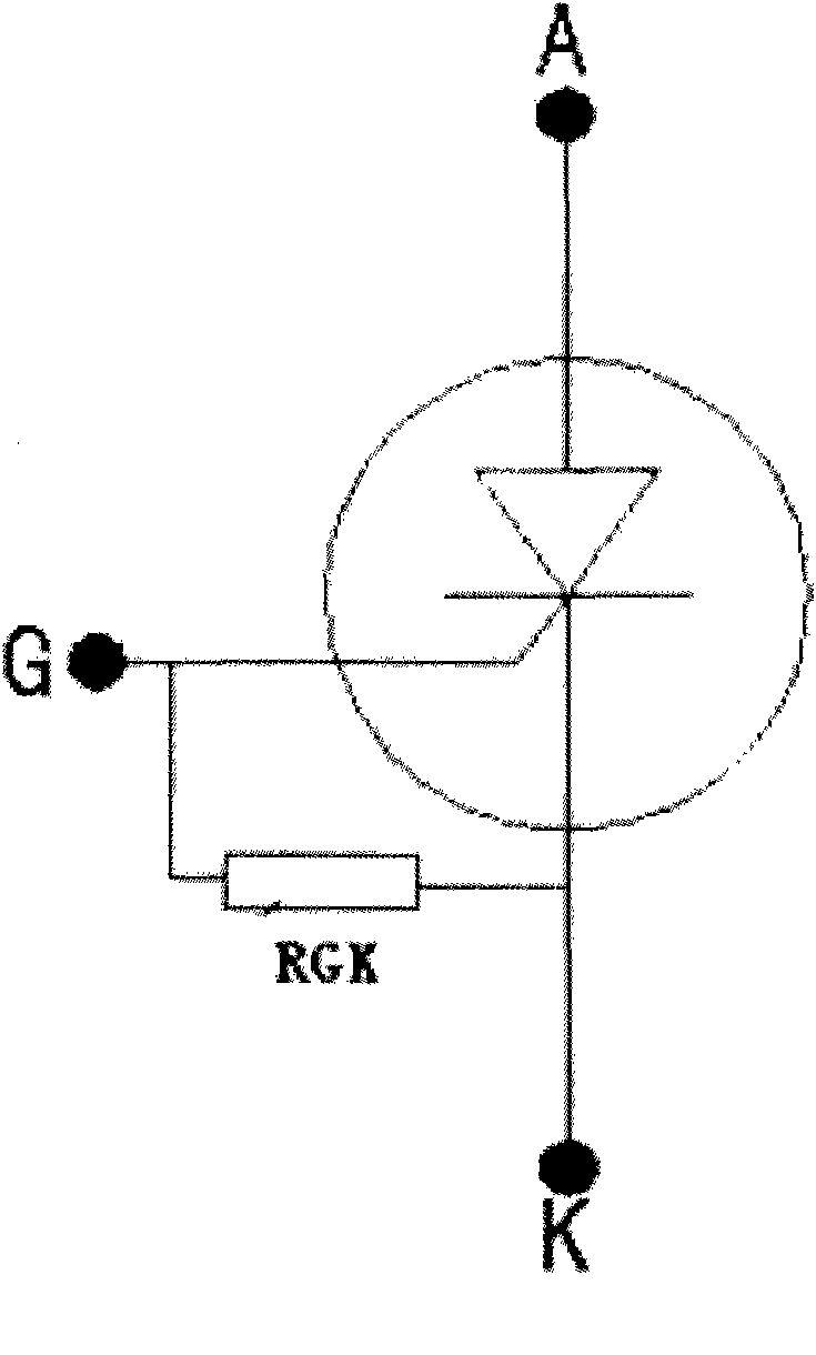
[0034] In the PNP structure near N + The emitter side is provided with a laterally integrated resistor R O , the laterally integrated resistor R O is a negative temperature coefficient type thermistor, and is connected between the gate electrode G and the cathode electrode K.

[0035] The laterally integrated resistor R O When the temperat...


PUM


Abstract

The invention discloses a weather-proof micro-trigger controlled silicon of a PNP structure. P-type silicon on one side of the PNP structure is provided with an N+ emitter region and a gate pole electrode, wherein the N+ emitter region is provided with a cathode electrode, and the P-type silicon on the other side of the PNP structure is provided with an anode electrode. A lateral integrated resistor is arranged in the PNP structure and is a negative temperature coefficient type thermistor which is connected between the gate pole electrode and the cathode electrode. The weather-proof micro-trigger controlled silicon of the invention has the technical characteristic of self adaption of self operating temperature variation, can adjust and match in due time according to the locating external atmosphere / ambient temperature, and has the capability of resisting temperature disturbance / resisting electromagnetic interference. In addition, the invention also discloses a manufacturing method of the weather-proof micro-trigger controlled silicon.

Description

technical field [0001] The invention relates to the technical field of semiconductors, in particular to a weather-resistant micro-trigger thyristor and a manufacturing method thereof. Background technique [0002] Since the successful development of the first industrial SCR in 1958 by General Electric Company of the United States, the conversion and control of electric energy has entered the era of converters composed of power semiconductor devices from rotating converter units and static ion converters. [0003] The main members of thyristors are unidirectional thyristors, bidirectional thyristors, light-controlled thyristors, reverse-conducting thyristors, turn-off thyristors and fast thyristors. Among them, the one-way thyristor is a controllable rectification electronic component, which can be turned from off to on under the action of an external control signal, but once it is turned on, the external signal cannot turn it off, and can only be removed load or reduce the ...

Claims


Application Information

Patent Timeline
Patent Type & Authority Applications(China)
IPC IPC(8): H01L27/06H01L29/74H01L21/77H01L21/332
Inventor 李文广周远铸
Owner 厦门泰格微电子科技有限公司
Learn More