Cylindrical permanent magnet linear motor with high thrust density
A permanent magnet linear motor, cylindrical technology, applied in the direction of electrical components, electromechanical devices, propulsion systems, etc., can solve the problems of low thrust density, poor overload capacity, etc., to improve thrust density, reduce processing difficulty and assembly clearance , Improve the effect of magnetic density
- Summary
- Abstract
- Description
- Claims
- Application Information
AI Technical Summary
Problems solved by technology
Method used
Image
Examples
specific Embodiment approach 1
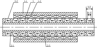
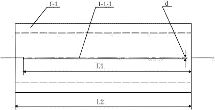
[0007] Specific implementation mode one: the following combination figure 1 and figure 2 Describe this embodiment, this embodiment includes a primary and a secondary, the primary is composed of an armature core 1-1 and an armature winding 1-2, the armature core 1-1 is cylindrical and made of a magnetically conductive material, the armature The iron core 1-1 is radially provided with a first through slot 1-1-1, the center line of the first through slot 1-1-1 is parallel to the axial direction of the motor, and the armature winding 1-2 is assembled on the armature core On the inner wall of 1-1, the armature winding 1-2 is composed of multiple pie-shaped windings arranged in a cylindrical shape in phase sequence, each pie-shaped winding is an independent winding, and the terminals of the multiple pie-shaped windings pass through the The first through slots 1-1-1 are connected to each other; there is an air gap 3 between the inner circular surface of the armature winding 1-2 an...
specific Embodiment approach 2
[0009] Specific implementation mode two: the following combination figure 1 and figure 2 This embodiment is described. The difference between this embodiment and Embodiment 1 is that the armature core 1-1 has a second through slot in the radial direction, and the center line of the second through slot is parallel to the axial direction of the motor. The size of the second through slot is equal to that of the first through slot 1-1-1 and they are oppositely arranged. The axial length L1 of the first through slot 1-1-1 is smaller than the axial length L2 of the armature core 1-1, so The terminals of the plurality of pie-shaped windings respectively pass through the first through slot 1-1-1 and the second through slot and are connected. Other components and connections are the same as those in Embodiment 1.
[0010] On the armature iron core 1-1, the first through groove 1-1-1 can be opened as required, and the first through groove 1-1-1 and the second through groove 1-1-1 ca...
specific Embodiment approach 3
[0012] Specific implementation mode three: combination figure 1 Describe this embodiment, this embodiment is a further description of Embodiment 1 or 2. In this embodiment, the surface where the long side of the isosceles trapezoidal section of the permanent magnet 2-2 is located is the inner ring surface of the permanent magnet 2-2. Other compositions and connections are the same as those in the first or second embodiment.
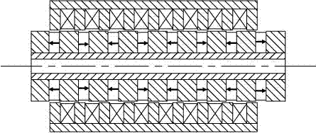
[0013] The inner ring surface of the permanent magnet 2-2 where the long side of the isosceles trapezoid is located matches the outer circular surface of the non-magnetic shaft tube 2-3, and the outer ring surface of the permanent magnet 2-2 where the short side of the isosceles trapezoid is located An air gap 3 is formed with the inner circular surface of the armature winding 1-2. A plurality of secondary iron cores 2-1 are respectively arranged between two adjacent permanent magnets 2-2, and the shape of the secondary iron cores 2-1 matches the perman...
PUM
 Abstract
Description
Claims
Application Information
 - R&D
- Intellectual Property
- Life Sciences
- Materials
- Tech Scout
- Unparalleled Data Quality
- Higher Quality Content
- 60% Fewer Hallucinations
Browse by: Latest US Patents, China's latest patents, Technical Efficacy Thesaurus, Application Domain, Technology Topic, Popular Technical Reports.
© 2025 PatSnap. All rights reserved.Legal|Privacy policy|Modern Slavery Act Transparency Statement|Sitemap|About US| Contact US: help@patsnap.com


