
Cathodic vacuum arc source film depositing device and method for depositing film

A thin film deposition device and vacuum arc technology, applied in vacuum evaporation plating, ion implantation plating, metal material coating technology, etc., can solve problems such as difficult to meet requirements, and achieve smooth surface, dense film structure, and uniform area big effect

Active Publication Date: 2010-08-04
NINGBO INST OF MATERIALS TECH & ENG CHINESE ACADEMY OF SCI
View PDF4 Cites 28 Cited by
  • Summary
  • Abstract
  • Description
  • Claims
  • Application Information

AI Technical Summary

Problems solved by technology

However, these kinds of magnetic filter elbows are still insufficient in reducing macroscopic large particles and improving the effective transmission of plasma, especially with the rapid development of modern large-capacity information storage, MEMS micro-electromechanical, aerospace and other high-tech fields, the traditional Cathodic vacuum arc source thin film deposition equipment is still difficult to meet the requirements in depositing ultra-hard and ultra-thin ta-C thin films

Method used


Image

  • Cathodic vacuum arc source film depositing device and method for depositing film
  • Cathodic vacuum arc source film depositing device and method for depositing film
  • Cathodic vacuum arc source film depositing device and method for depositing film

Examples


Embodiment Construction

[0033] The present invention will be further described in detail below in conjunction with the accompanying drawings and embodiments.

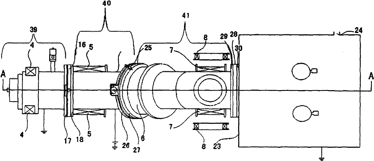
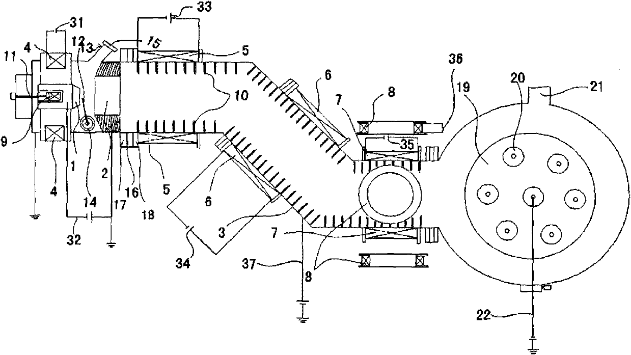
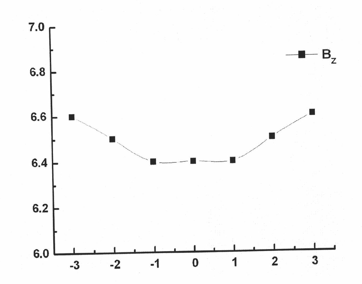
[0034] Figure 1 to Figure 7 Shown is the structural representation of the present invention.

[0035] The reference signs therein are: cathode 1, anode 2, elbow 3, arc source coil 4, pulling coil 5, bending coil 6, output coil 7, scanning coil 8, permanent magnet 9, grid baffle 10, Threaded rod 11, trigger electrode 12, gas channel 13, pneumatic valve 14, observation window 15, insulating washer 16, stainless steel ring 17, stainless steel ring 18, large disk 19, small disk 20, air inlet 21, bias power supply 22, film deposition Vacuum chamber 23, vent port 24, insulating gasket 25, stainless steel ring 26, stainless steel ring 27, insulating gasket 28, stainless steel ring 29, stainless steel ring 30, arc source coil DC power supply 31, arc pulse power supply 32, pull coil DC power supply 33 , bending coil DC power supply 34, output coil D...


PUM

PropertyMeasurementUnit
angleaaaaaaaaaa
thicknessaaaaaaaaaa
elastic modulusaaaaaaaaaa

Abstract

The invention discloses a cathodic vacuum arc source film depositing device which comprises a magnetic filtering part capable of transferring plasma at high speed and effectively filtering macro-large particles, wherein the magnetic filtering part comprises a tube body and a magnetic field generator which is arranged at the external periphery of the tube body; the tube body comprises an inlet end surface of the tube body and an outlet end surface of the tube body, at least one bent tube is arranged between the inlet end surface of the tube body and the outlet end surface of the tube body, and an included angle between the axial lines of the tube body at two sides of the bent tube is 135 degrees; and the introducing amount of inert gases in the device is 10-50sccm, and the vacuum degree is 1.0*10-5 to 5.0*10-5Torr after the device is vacuumized. Compared with the prior art, the cathodic vacuum arc source film depositing device of the invention can realize the purposes of effectively filtering macro-large particles and simultaneously transferring plasma at high speed, thereby improving the quality and the deposition rate of the film. The method of the invention can be used for depositing the film at high speed, the deposited film has compact structure, smooth surface and large uniform region area, and the method can be used for depositing high-performance ta-C films.

Description

technical field [0001] The invention relates to a cathode vacuum arc source thin film deposition device and a thin film deposition method using the device. Background technique [0002] The cathodic vacuum arc deposition method is a method in which the plasma generated by the vacuum arc evaporation source is attracted to the substrate by means of a negative bias voltage, etc., and a thin film is formed on the surface of the substrate. Wherein, the cathode vacuum arc evaporation source evaporates the cathode target by vacuum arc discharge, thereby generating plasma containing the cathode target material. The cathodic vacuum arc deposition method has a series of advantages such as high ionization rate, high ion energy, low deposition temperature, high deposition rate, and good film-substrate bonding. Therefore, it is not only the main method for depositing traditional TiN, CrN, TiAlN and other hard films. method, and it is also one of the most promising methods for depositing...

Claims


Application Information

Patent Timeline
Patent Type & Authority Applications(China)
IPC IPC(8): C23C14/24C23C14/54
Inventor 汪爱英李洪波柯培玲
Owner NINGBO INST OF MATERIALS TECH & ENG CHINESE ACADEMY OF SCI
Learn More