Eureka AIR delivers breakthrough ideas for toughest innovation challenges, trusted by R&D personnel around the world.

Unit cell of fuel battery

A fuel cell and single cell technology, applied in the direction of fuel cells, fuel cell parts, battery electrodes, etc., can solve problems such as increased load, increased mechanical load of electrolyte membrane, and insufficient application

Inactive Publication Date: 2010-07-28
TOYOTA JIDOSHA KK
View PDF1 Cites 9 Cited by
  • Summary
  • Abstract
  • Description
  • Claims
  • Application Information

AI Technical Summary

Problems solved by technology

[0019] As a result, when a plurality of single cells are stacked to generate power, the load per unit area of ​​the outer peripheral portion of the single cell increases, thereby causing a problem that the dynamic load acting on the electrolyte membrane increases.
In addition, since a sufficient load per unit area cannot be applied to the central part of the single cell that plays a major role in power generation, there is also a problem that sufficient power generation cannot be performed as designed.

Method used


Image

  • Unit cell of fuel battery
  • Unit cell of fuel battery
  • Unit cell of fuel battery

Examples


Embodiment Construction

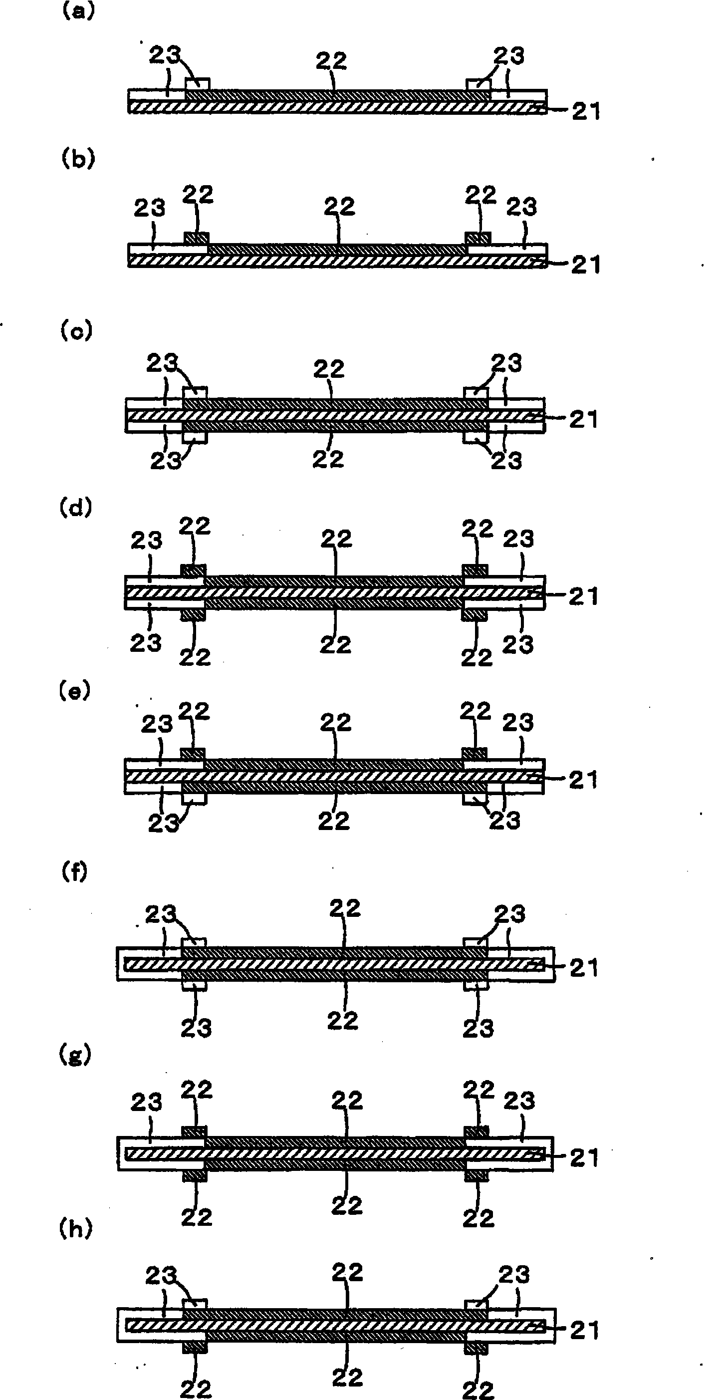
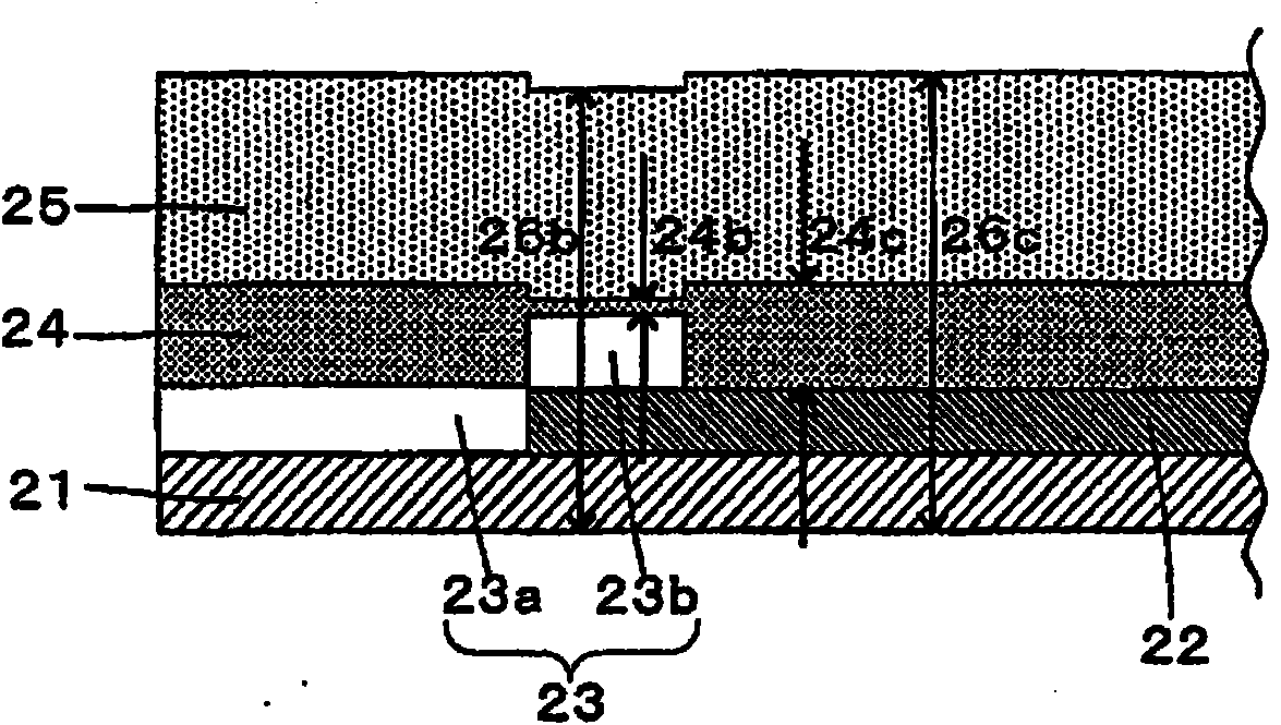
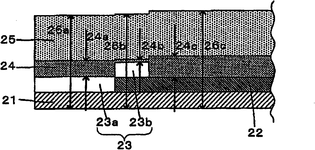
[0111] A unit cell of a fuel cell according to the present invention has a membrane electrode assembly having an anode electrode including an anode catalyst layer and a gas diffusion layer on one side of a solid polymer electrolyte membrane, and a pair of separators, and on the other side of the solid polymer electrolyte membrane. One side has a cathode electrode including a cathode catalyst layer and a gas diffusion layer, and the unit cell of the above-mentioned fuel cell is characterized in that, on at least one side of the anode side and the cathode side of the above-mentioned solid polymer electrolyte membrane, the above-mentioned anode or cathode catalyst layer It has a size and shape slightly smaller than that of the solid polymer electrolyte membrane and the gas diffusion layer, and the outer peripheral portion of the solid polymer electrolyte membrane and the gas diffusion layer exposed from the outer periphery of the anode or cathode catalyst layer The outer periphera...


PUM

PropertyMeasurementUnit
thicknessaaaaaaaaaa
thicknessaaaaaaaaaa
thicknessaaaaaaaaaa

Abstract

A unit cell of a fuel battery such that the mechanical load on the electrolyte membrane is lightened and an adequate load per unit area can be exerted on the central part. The unit cell comprises a membrane electrode assembly which has an anode electrode provided on one side of a solid polymer electrolyte film and including an anode catalyst layer and a gas diffusing layer and a cathode electrode provided on the other and including a cathode catalyst layer and a gas diffusing layer and a pair of separators. The unit cell is characterized in that at least on one side of the anode and cathode sides of the solid polymer electrolyte film, the anode or cathode catalyst layer has dimensions and a shape a size smaller than those of the solid polymer electrolyte film and the gas diffusion layers, the outer periphery of the solid polymer electrolyte film protruding from the periphery of the anode or cathode catalyst layer is opposed to the outer periphery of the gas diffusing layer, a protective layer having a picture-frame shape and having a first portion interposed between the outer periphery of the solid polymer electrolyte film and the outer periphery of the gas diffusing layer and a second portion placed on the outer periphery of the anode or cathode catalyst layer is provided, and a unit cell thickness adjustment layer is provided in which the thickness of the unit cell thickness adjustment layer in the region where the second portion of the protective layer is present is smaller than the thickness of the unit cell thickness adjustment layer in the central region where the protective layer is not present or the unit cell thickness adjustment layer is not provided so that the thickness of the unit cell in the region where the second portion of the protective layer is present may be the thickness or less of the unit cell in the central region.

Description

technical field [0001] The invention relates to a single cell of a fuel cell. Background technique [0002] A fuel cell supplies fuel and an oxidant to electrically connected two electrodes, electrochemically causes oxidation of the fuel, thereby directly converting chemical energy into electrical energy. Unlike thermal power generation, fuel cells are not constrained by the Carnot cycle and thus exhibit high energy conversion efficiency. A fuel cell is generally constituted by stacking a plurality of unit cells, and the unit cell has a basic structure of a membrane electrode assembly in which an electrolyte membrane is sandwiched between a pair of electrodes. Among them, solid polymer electrolyte fuel cells that use solid polymer electrolyte membranes as electrolyte membranes have the advantages of being easy to miniaturize and operating at low temperatures. Therefore, they are attracting attention as power sources for portable and mobile bodies. . [0003] In a solid po...

Claims


Application Information

Patent Timeline
Patent Type & Authority Applications(China)
IPC IPC(8): H01M8/02H01M4/86H01M8/10
CPCH01M8/0273Y02E60/521H01M4/8615H01M8/1004Y02E60/50
Inventor 雫文成西山博史
Owner TOYOTA JIDOSHA KK
Why Eureka
Eureka Blog
Learn More