
Semiconductor device and manufacturing method thereof

A manufacturing method, semiconductor technology, applied in the direction of semiconductor/solid-state device manufacturing, semiconductor devices, semiconductor/solid-state device components, etc., can solve the problems of reading quality degradation and confusion of mark 10

Active Publication Date: 2010-07-28
SEMICON MFG INT (SHANGHAI) CORP +1
View PDF1 Cites 17 Cited by
  • Summary
  • Abstract
  • Description
  • Claims
  • Application Information

AI Technical Summary

Problems solved by technology

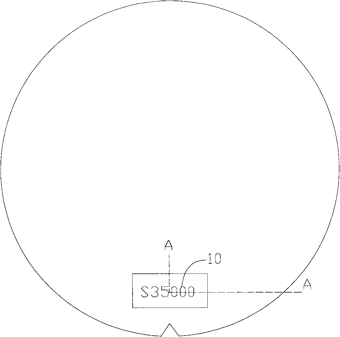
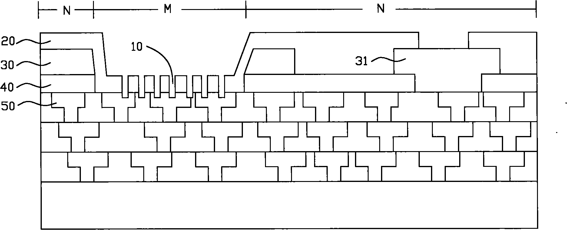
[0006] Although the above-mentioned semiconductor device forms an effective circuit in the marking area M, the problem is that the mark 10 of the semiconductor wafer is engraved in the last metal interconnection layer 50, so that the final metal interconnection layer 50 The pattern of the mark 10 is confused with the pattern of the mark 10, resulting in a degradation of the reading quality of the mark 10

Method used


Image

  • Semiconductor device and manufacturing method thereof
  • Semiconductor device and manufacturing method thereof
  • Semiconductor device and manufacturing method thereof

Examples


Embodiment Construction

[0058] In order to make the above objects, features and advantages of the present invention more comprehensible, specific implementations of the present invention will be described in detail below in conjunction with the accompanying drawings.

[0059] In the following description, a lot of specific details are set forth in order to fully understand the present invention, but the present invention can also be implemented in other ways different from those described here, and those skilled in the art can do it without departing from the meaning of the present invention. By analogy, the present invention is therefore not limited to the specific examples disclosed below.

[0060] Secondly, the present invention is described in detail in combination with schematic diagrams. When describing the embodiments of the present invention in detail, for the convenience of explanation, the cross-sectional view showing the device structure will not be partially enlarged according to the general...


PUM


Abstract

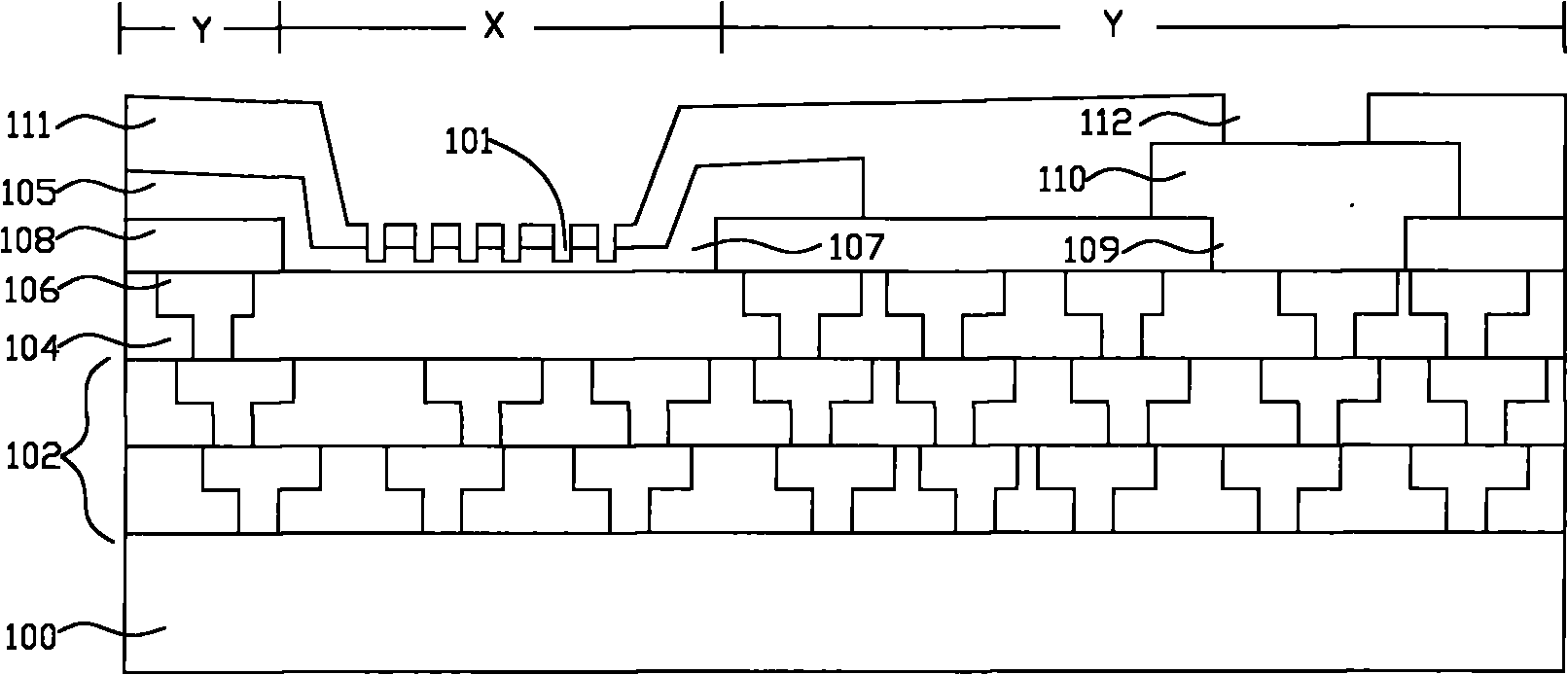
The invention provides a semiconductor device and a manufacturing method thereof. The manufacturing method comprises the following steps of: providing a semiconductor chip; embedding the final layer of metal interconnection layer in a dielectric layer in a chip region; forming a first passivation layer on the final layer of metal interconnection layer in the chip region, wherein a soldering pad opening is arranged at a position in the first passivation layer corresponding to the final layer of metal interconnection layer; forming a metal layer which covers on a dielectric layer in a marking region and the first passivation layer in the chip region, and forming a soldering pad layer connected with the final layer of metal interconnection layer from the metal layer in the chip region; forming a second passivation layer which covers on the metal layer in the marking region and the soldering pad layer in the chip region, wherein a top layer opening is arranged at a position in the second passivation layer corresponding to the soldering pad layer; and forming a mark of the semiconductor chip in the marking region, wherein the mark is embedded into the second passivation layer and the metal layer. The device and the manufacturing method can form an effective circuit in the marking region and obtain the distinct semiconductor chip mark.

Description

technical field [0001] The invention relates to the technical field of semiconductor manufacturing, in particular to a semiconductor device and a manufacturing method thereof. Background technique [0002] In the semiconductor manufacturing process, it is usually necessary to use a laser to engrave a mark (IDmark) on the edge of the wafer to record information such as the batch number of the semiconductor wafer. In the initial manufacturing process of semiconductor wafers below 8 inches, marks are usually directly engraved on the polished semiconductor wafers before entering the normal manufacturing process, while in the manufacturing process of 12-inch semiconductor wafers, often after all the manufacturing processes are completed, Markings are engraved on the uppermost passivation layer. [0003] Usually, the area where the mark is engraved is no longer used to make the semiconductor device, so as to prevent the pattern of the semiconductor device from covering the mark, ...

Claims


Application Information

Patent Timeline
IPC IPC(8): H01L21/768H01L21/268H01L23/528H01L23/544
Inventor 武咏琴
Owner SEMICON MFG INT (SHANGHAI) CORP
Learn More