Two-control three-precharge phase-control switch circuit of switched capacitor bank

A technology of switching capacitors and phase-controlled switches, which is applied in AC networks to reduce harmonics/ripples, reactive power compensation, harmonic reduction devices, etc., and can solve the problems of high energy consumption, shortened operation time, and low switching accuracy. , to achieve the effect of high quality, low cost and no energy consumption

Active Publication Date: 2010-07-21
北京馨容纵横科技发展有限公司
View PDF3 Cites 11 Cited by
  • Summary
  • Abstract
  • Description
  • Claims
  • Application Information

AI Technical Summary

Problems solved by technology

[0008] The invention creates a new type of switching circuit. Its positioning: reversing the situation that TCR+FC dominates the world in the field of medium voltage dynamic compensation; The slow speed limit of the control switch shortens the action time, and completes an action from opening to closing within 1 second. There is no current impact when closing, and the opening current is zero; the traditional three-phase phase control switch uses three The st

Method used


Image

  • Two-control three-precharge phase-control switch circuit of switched capacitor bank
  • Two-control three-precharge phase-control switch circuit of switched capacitor bank
  • Two-control three-precharge phase-control switch circuit of switched capacitor bank

Examples


Embodiment Construction

[0029] to see Figure 1-10 .

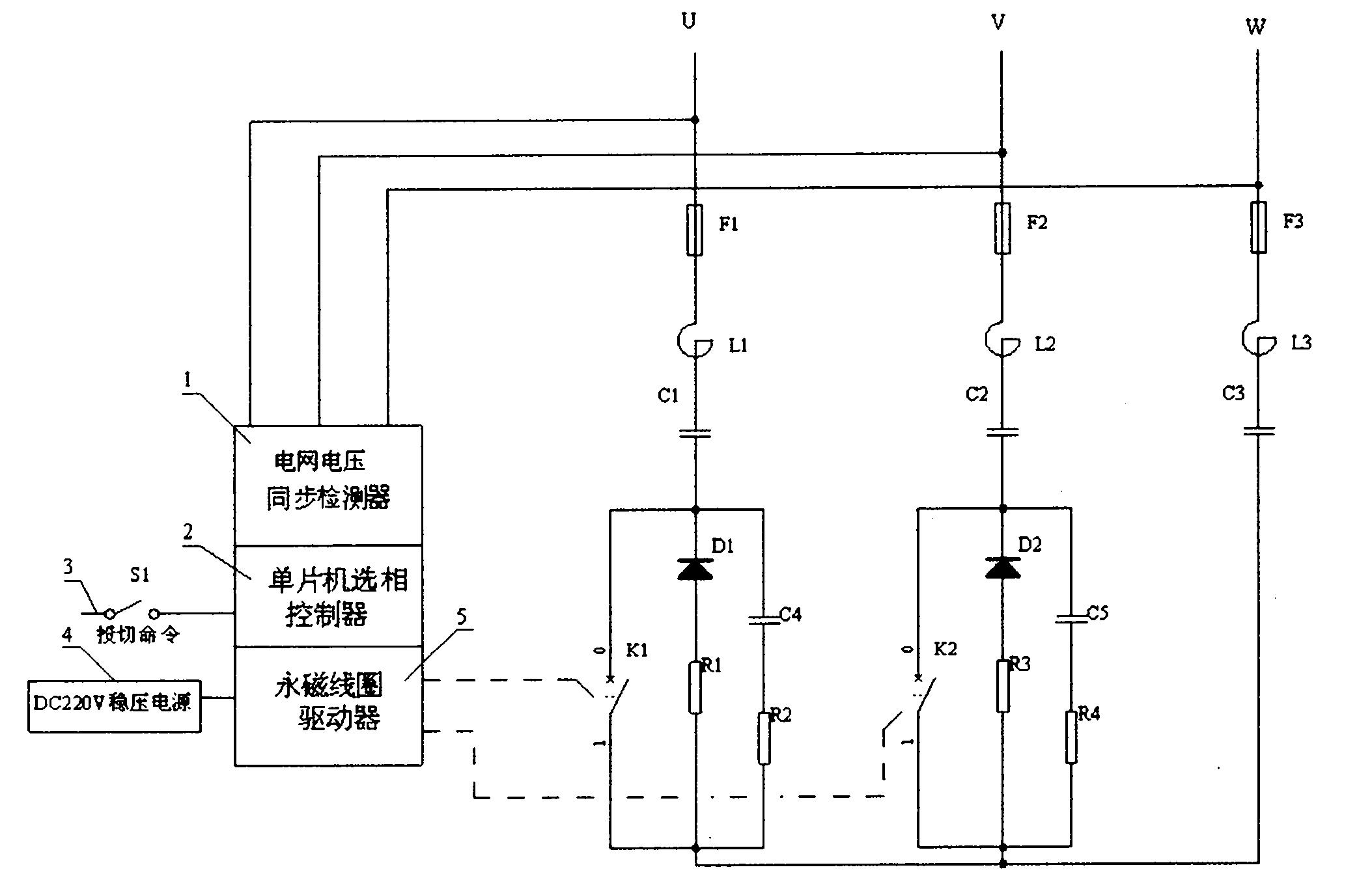
[0030] please see Figure 1-Figure 7 : Two phase-controlled switches K1 and switch K2 for precharging the capacitor bank form a 3-phase zero-point switch. A series circuit of a high-voltage silicon stack diode D1 and a high-voltage current-limiting resistor R1 is connected in parallel next to the switch K1 to achieve the pre-charging of the capacitor bank. Function; at the same time, the series absorption circuit of capacitor C4 and resistor R2 is connected in parallel to absorb the rapidly changing voltage on switch K1. The series circuit of high-voltage silicon stack diode D2 and high-voltage current-limiting resistor R3 is connected in parallel next to switch K2 to achieve the effect of precharging the capacitor bank; at the same time, the series circuit of capacitor C5 and resistor R4 is connected in parallel, and the absorption switch K2 quickly changing voltage. The input end of switch K1 is connected with the series filter circuit of re...


PUM


Abstract

The invention relates to a two-control three-precharge phase-control switch circuit of a switched capacitor bank, which comprises a three-phase zero switch which consists of two phase-control switches for pre-charging the capacitor bank, the input end of the two phase-control switches is connected with a casecade filtering circuit of a two-phase star connection, the output end of the two phase-control switches is connected with an LC filter circuit of a third phase after being connected with each other, the LC filter circuit of star connection is connected with a three-phase electric-net power source through a high-voltage fuse, and a phase control device independently controls the connection and the disconnection of the two phase-control switches at the peak point of the voltage according to the time order. A casecade circuit of a high-voltage silicon-stack diode and a high-voltage current-limiting resistor is connected with each phase-control switch in parallel so as to realize the pre-charging of the capacitor bank; and at the same time a casecade absorption circuit of RC is connected with each phase-control switch in parallel. The tested waveform shows that: the switching effect of the two-control three-precharge phase-control switch circuit can be switched one time without impact within one second like the TSC (thyristor switched capacitor bank), is free from the power consumption, adopts an ordinary switch as a phase-control switch, and has low cost.

Description

technical field [0001] The invention relates to a 2-control 3 pre-charging phase-controlled switch circuit for switching capacitor banks, which is used in the power quality control project of the power grid, and can realize fast and non-impact current input to the capacitor bank and cut off when the current crosses zero, belonging to the power system The field of reactive power compensation and harmonic filtering technology. Background technique [0002] The conventional circuit of switching capacitor bank is: mechanical contact switching switch, thyristor switching capacitor (TSC), synchronous vacuum switch. [0003] Mechanical contact switching switch, three-phase switch switches capacitors at random and uncertain grid voltage points, the current impact is large, and the rated current is at least a few times, causing grid voltage distortion. There is also a dangerous probability of bouncing of the closing mechanical contact and re-ignition of the open contact. The re-igni...

Claims


Application Information

Patent Timeline
IPC IPC(8): H02J3/18H02J3/01
CPCY02E40/30Y02E40/40
Inventor 杨建宁
Owner 北京馨容纵横科技发展有限公司
Why Eureka
Try Eureka