Cantilever beam type accelerometer based on photonic crystal microcavity

A photonic crystal microcavity and cantilever beam technology, which is applied in the direction of measurement of acceleration, velocity/acceleration/shock measurement, optical waveguide coupling, etc., can solve the problems of difficult improvement of performance parameters such as resolution and sensitivity, and expand the scope of application , Small size, high measurement accuracy

Inactive Publication Date: 2011-06-29
ZHONGBEI UNIV
View PDF1 Cites 0 Cited by
  • Summary
  • Abstract
  • Description
  • Claims
  • Application Information

AI Technical Summary

Problems solved by technology

However, under the rapid development in recent years, the cantilever beam accelerometer based on the above-mentioned sensitive elements has been developed to the limit, and it is not easy to improve its performance parameters such as resolution and sensitivity.

Method used


Image

  • Cantilever beam type accelerometer based on photonic crystal microcavity
  • Cantilever beam type accelerometer based on photonic crystal microcavity
  • Cantilever beam type accelerometer based on photonic crystal microcavity

Examples


Embodiment Construction

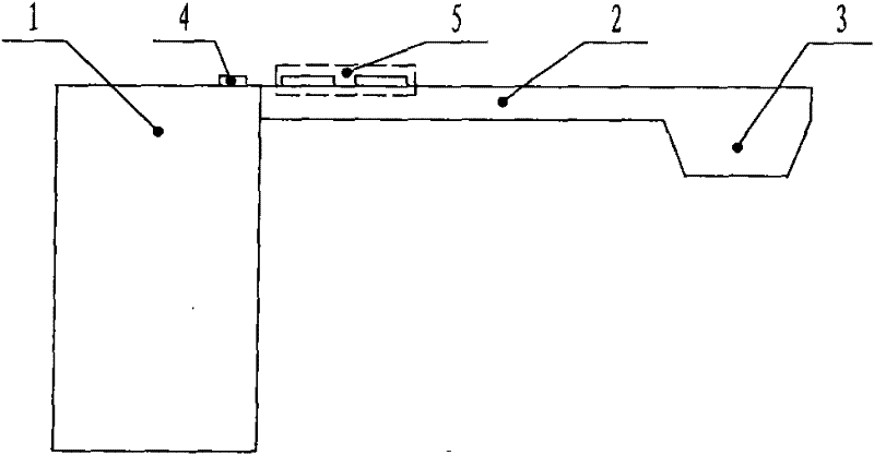
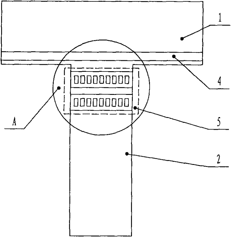
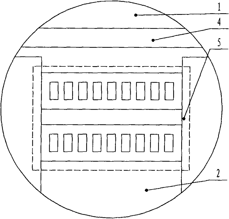
[0017] Such as Figure 1-3 As shown, the cantilever beam accelerometer based on the photonic crystal microcavity includes the base 1 processed on the semiconductor substrate by the micro-electromechanical device processing technology (MEMS processing technology), and the cantilever beam fixed to the base 1 at one end 2. The mass block 3 fixed to the free end of the cantilever beam 2, the base 1 is provided with an optical waveguide 4 perpendicular to the cantilever beam 2, and the end of the cantilever beam 2 fixed to the base 1 is provided with a "zipper cavity (Zippercarity) 5. The two brackets of the "zipper cavity" 5 are parallel to the optical waveguide 4 on the base 1, and the "zipper cavity" 5 and the optical waveguide 4 form a microcavity-optical waveguide coupling structure.

[0018] During specific implementation, the material of the "zipper hole" 5 is silicon nitride Si 3 N 4 , the material of the optical waveguide is silicon dioxide SiO 2 In the cantilever beam ...


PUM


Abstract

The invention relates to an optical and microelectromechanical technology, in particular to a cantilever beam type accelerometer based on a photonic crystal microcavity. The application of the photonic microcavity in the cantilever beam type accelerometer is further expanded. The cantilever beam type accelerometer based on the photonic crystal microcavity comprises a base, a cantilever beam and amass block, wherein the base is processed on a semiconductor substrate by a processing process of a microelectromechanical device; the single end of the cantilever beam is fixed to the base; the massblock is fixed to the free end of the cantilever beam; an optical waveguide which is perpendicular to the cantilever beam is arranged on the base; the end part of the cantilever beam, which is fixed to the base, is provided with a zipper cavity; two brackets of the zipper cavity are parallel to the optical waveguide on the base; and the zipper cavity and the optical waveguide form a microcavity-optical waveguide coupling structure. The invention has reasonable and simple structure and good characteristics of high sensitivity, high resolution, high measurement precision, electromagnetic interference resistance, small size, convenient integration, light weight, operation in severe environment, wide application range, and the like.

Description

technical field [0001] The invention relates to optics and micro-electromechanical technology, in particular to a cantilever beam accelerometer based on a photonic crystal microcavity. Background technique [0002] Micro-electromechanical accelerometers are important sensors commonly used in the fields of machinery, vehicles, ships, etc. for shock resistance and vibration measurement, earthquake monitoring, inertial navigation and guidance systems, etc. Among them, the cantilever beam accelerometer in the micro-electromechanical accelerometer has the advantages of small size, good resolution and sensitivity, and easy mass production. 1. The mass block fixed to the free end of the cantilever beam. The fixed end of the cantilever beam and the base is equipped with a sensitive element. The working principle is: under the action of inertial force, the mass block moves up and down, causing the cantilever beam to deform and produce stress changes. , so that the state of the sensi...

Claims


Application Information

Patent Timeline
Patent Type & Authority Patents(China)
IPC IPC(8): G01P15/093B81B7/02
Inventor 刘俊闫树斌张文栋熊继军刘正石云波
Owner ZHONGBEI UNIV
Why Eureka
Try Eureka