Drying device with effects of energy conservation and environmental protection

A drying equipment, energy-saving and environmental protection technology, applied in drying, dryer, lighting and heating equipment and other directions, can solve the problems of polluting gas, waste of heat source, consumption of large energy, etc., to achieve low heat loss, low additional loss, Make full use of the effect of thermal energy

Inactive Publication Date: 2011-06-15
FUJIAN GUANGHUILONG ENVIRONMENTAL PROTECTION TECH
View PDF0 Cites 0 Cited by
  • Summary
  • Abstract
  • Description
  • Claims
  • Application Information

AI Technical Summary

Problems solved by technology

[0004] The invention provides a drying equipment with energy saving and environmental protection effects, the main purpose of which is to overcome the shortcomings of the existing drying equipment such as consuming a large amount of energy, emitting a large amount of polluted gas, and wasting heat sources.

Method used


Image

  • Drying device with effects of energy conservation and environmental protection
  • Drying device with effects of energy conservation and environmental protection
  • Drying device with effects of energy conservation and environmental protection

Examples


Embodiment 1

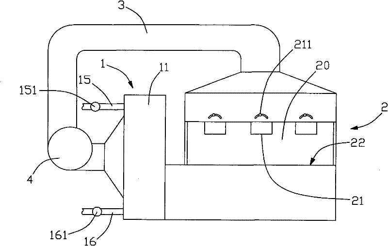
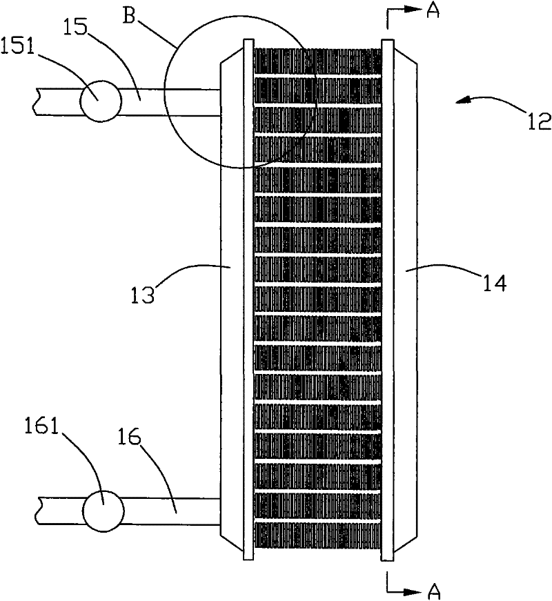
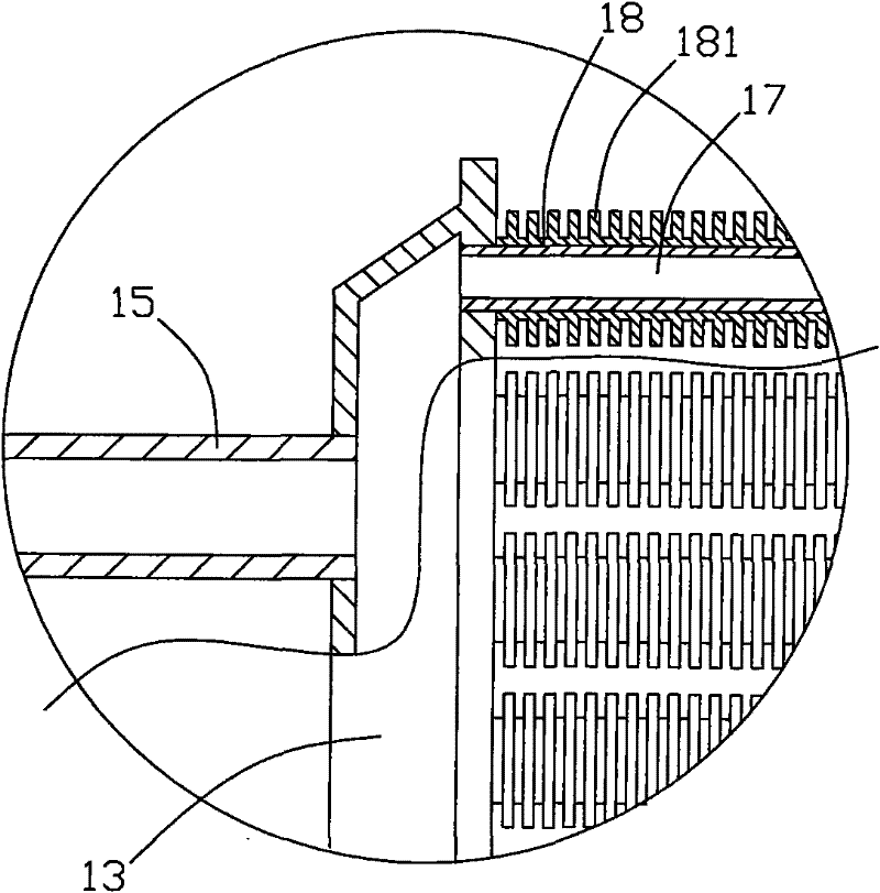
[0027] A kind of drying equipment with energy saving and environmental protection effect, refer to figure 1 , including a heating device 1 and a working box 2. refer to figure 1 and figure 2 , the heating device 1 includes a heating box 11, the heating box 11 is provided with a heating body 12, the heating body 12 is provided with a hot gas inlet 15 and a discharge port 16 connected to the inner cavity, and the hot gas inlet 15 is filled with hot waste gas Or high-temperature steam, hot waste gas or high-temperature steam exchanges heat with the heating element 12, and discharges condensed water and partially cooled gas at the discharge port 16. Therefore, the drying equipment can make full use of the waste heat discharged from the existing factory or the high-temperature steam generated by the existing boiler as a heat source, without consuming additional electricity, coal, oil energy, and will not generate additional polluting gas emissions. The drained condensate can al...

Embodiment 2

[0035] refer to Figure 5 , the structure and principle of this embodiment are basically the same as that of Embodiment 1, the difference is that an air outlet 21 is provided on the top of the working space 20, and the air outlet 21 communicates with the air outlet of the heating box 1, and the bottom of the side wall is provided with an air outlet 21. There is an air suction port, and the air suction port communicates with the air inlet of the heating box 1 , and the working space 20 is provided with a conveying device 23 for moving the to-be-dried objects in the working space. This embodiment is suitable for larger workpieces, and the conveying device 23 can be a belt conveying device, a chain conveying device, etc. according to specific needs.

[0036] This embodiment may also include a control box, which is connected with the frequency conversion fan 4, the pressure control valves 151, 161 and the conveying device 23 to realize comprehensive control.


PUM


Abstract

The invention relates to a drying device with effects of energy conservation and environmental protection, which comprises a heating device and a working box, wherein the heating device comprises a heating box which is internally provided with a heating body; the surface of the heating body is provided with a radiating fin, and a closed cavity is formed inside the heating body; the heating body is provided with a hot air inlet and a discharge hole which are communicated with the closed cavity; the working box is internally formed with a working space used for placing dried articles; the working space is communicated with the heating box by a ventilating duct so that a circulating pipeline can be formed; and the circulating pipeline is internally provided with a fan leading the air to circulate inside the pipeline. The drying device fully utilizes waste heat emitted by the existing plants or high temperature steam produced by the existing boiler as a heat source, does not need to consume extra energy such as electricity, coal and oil, does not emit extra pollution gas, fully uses the heat source, and leads useless heat loss to be minimized.

Description

technical field [0001] The invention relates to a drying device, in particular to a drying equipment with energy saving and environmental protection effects. Background technique [0002] Drying equipment is widely used in various industrial fields such as food, feed, chemical industry, medicine, mining, metallurgy, electroplating, etc. The main principle is to heat the air in the working space, or let the heated air flow into the working space to make the working Moisture on wet items in the space evaporates and dries. [0003] The heat source of the above-mentioned drying equipment comes from a heating device, which usually includes an electric heating device and a combustion device. This heating device is usually accompanied by a large amount of energy consumption such as electricity, coal, oil, etc., and will produce a large amount of polluting gas emissions. Comply with the environmental protection policy of energy saving and emission reduction. Moreover, after the ho...

Claims


Application Information

Patent Timeline
Patent Type & Authority Patents(China)
IPC IPC(8): F26B9/06F26B3/06F26B21/02
Inventor 唐宏军
Owner FUJIAN GUANGHUILONG ENVIRONMENTAL PROTECTION TECH
Why Eureka
Try Eureka