
Excavator swing arm descending hydraulic control loop

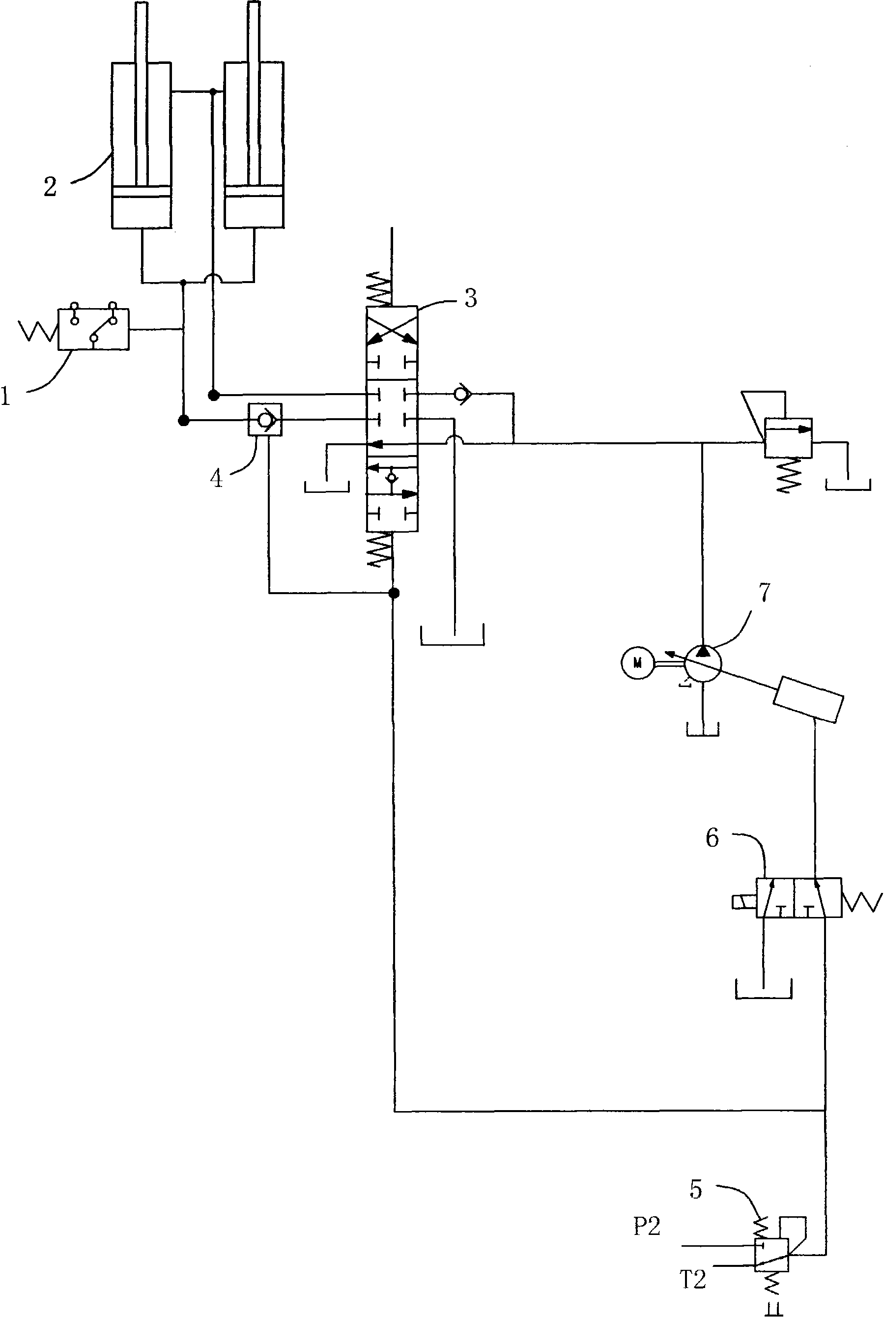
A technology of control circuit and mobile arm, which is applied in the direction of earth mover/shovel, construction, etc., can solve the problems of increased displacement, negative pressure of the arm, and lack of reception, so as to prevent the phenomenon of suction and reduce the system Effect of oil temperature and power consumption reduction

Active Publication Date: 2010-07-14
QINGDAO LOVOL EXCAVATOR
View PDF0 Cites 17 Cited by
  • Summary
  • Abstract
  • Description
  • Claims
  • Application Information

AI Technical Summary

Problems solved by technology

If the displacement of the hydraulic pump continues to increase at this time, it will not only cause waste of energy, but also cause adverse phenomena such as system heating.
[0004] If the boom lowering pilot signal is cut off and the hydraulic pump is connected to the oil circuit, the boom can be lowered completely by its own weight adjustment, but this will also encounter the following problems: First, when the boom is lowered too fast, the regenerated oil The amount is far behind the speed of the boom's lowering, which will cause negative pressure in the rod cavity of the boom (that is, the phenomenon of suction), which is not allowed; secondly, when the bucket touches the ground, it will often perform the action of lowering the boom. Realize the working conditions of supporting the car, leveling the ground, etc. However, at this time, the conversion of potential energy and hydraulic energy is no longer performed to achieve the oil supply to the rod cavity of the boom cylinder
However, because the hydraulic pump is disconnected from the oil circuit connected to the boom lowering pilot signal, it cannot receive the command to increase the displacement and supply oil to the rod chamber of the boom cylinder. At this time, although the pilot handle sends out the boom lowering command command, but the boom cylinder will not move

Method used


Image

  • Excavator swing arm descending hydraulic control loop
  • Excavator swing arm descending hydraulic control loop

Examples


Embodiment Construction

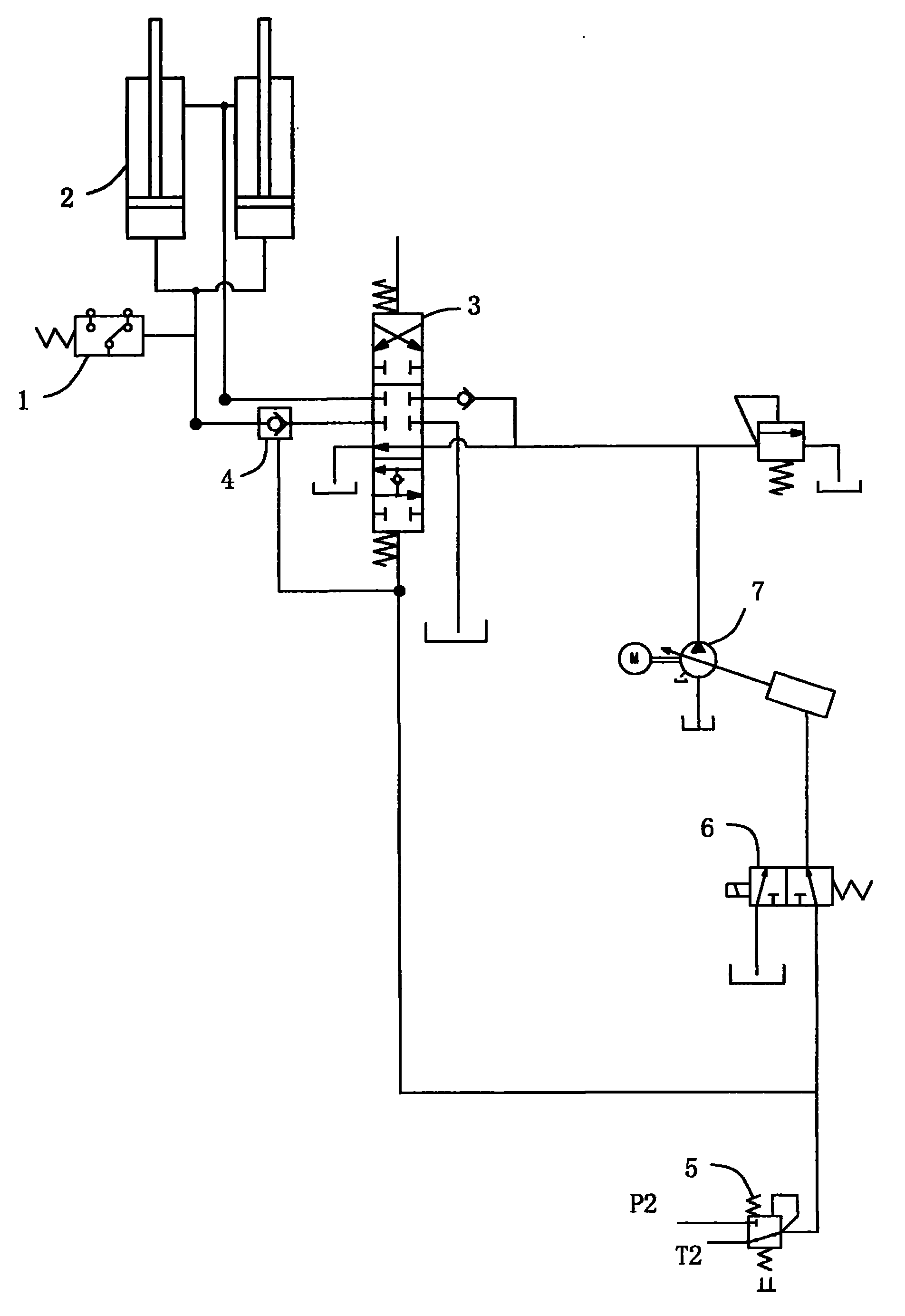
[0013] As shown in the drawings, a hydraulic control circuit for excavator boom lowering includes a variable displacement hydraulic pump 7 controlled by a servo variable mechanism connected through pipelines, a boom bidirectional hydraulic control reversing valve 3 and a boom cylinder 2 .

[0014] The servo variable mechanism is a well-known mechanism, and its usual structure is to set a servo piston in the housing, and the servo piston is connected to a swash plate through a hinge, and the swash plate swing angle can be changed when the hydraulic oil pushes the piston to move. size, thereby changing the displacement of the variable displacement hydraulic pump 7.

[0015] The boom two-way hydraulic control reversing valve 3 is preferably a three-position six-way two-way hydraulic control reversing valve with regeneration function (for the so-called "regeneration", refer to the second paragraph of the background technology part), the three-position six-way two-way hydraulic con...


PUM


Abstract

The invention discloses an excavator swing arm descending hydraulic control loop. The key points of design are as follows: an electromagnetic directional valve is arranged between a servo variable mechanism of a emission variable hydraulic pump and an oil outlet of a swing arm descending manual pilot valve; a hydraulic controlled electric contact pressure switch is arranged on the connecting pipeline between a rodless cavity of a swing arm cylinder and a swing arm two-way hydraulic controlled directional valve, and the electric contact pressure switch is electrically connected with the electromagnetic directional valve; the spool of the swing arm two-way hydraulic controlled directional valve is provided with a compensation channel, and the compensation channel is internally provided with a one-way valve. When the swing arm descends, under actions of the swing arm and the load gravity thereof, hydraulic oil supposed to flow back to an oil tank enters into a rod cavity quickly via the compensation channel, while the emission variable hydraulic pump maintains in the lowest emission state, thus reducing power consumption, lowering system oil temperature and saving energy. And when the swing arm descends too quickly or the bucket nearly touches with the ground, the air suction phenomenon is avoided from occurring, and the swing arm cylinder is under reliable control all the time.

Description

technical field [0001] The invention relates to an excavator hydraulic system, in particular to an excavator boom lowering hydraulic control circuit. Background technique [0002] The positive flow control system has been used more and more in medium and large excavators. The so-called positive flow control system is different from the previous negative flow control system. The positive flow control system refers to the displacement of the hydraulic pump and the pilot operating handle. The output signal pressure is proportional, the main controller judges the flow demand of the actuator and its change trend according to the pilot pressure signal and its change trend, and adjusts the displacement of the hydraulic pump accordingly, and the flow supply of the system can dynamically follow the actuator Real-time matching of system traffic, that is, "what you get is what you need". [0003] According to the principle of positive flow, when the pilot handle is operated to lower t...

Claims


Application Information

Patent Timeline
Patent Type & Authority Applications(China)
IPC IPC(8): E02F9/22
Inventor 张博友胡学军陈志强张军荣李兵李小亮张玮夏金玲曲海斌胡月平刘靖宇周文涛李亮宇
Owner QINGDAO LOVOL EXCAVATOR
Learn More