
Multi-channel serially connected lithium battery detector

A lithium battery, multi-channel technology, applied in the direction of instruments, measuring electricity, measuring devices, etc., can solve the measurement requirements that cannot meet the high voltage and high precision, cannot meet the high voltage and high precision measurement requirements, and the battery detection device is large in size, etc. problems, to achieve excellent test performance, meet the requirements of high voltage and high precision detection, and expand the voltage measurement range.

Inactive Publication Date: 2010-07-07
XIAN SAFTY ENERGY TECH
View PDF0 Cites 8 Cited by
  • Summary
  • Abstract
  • Description
  • Claims
  • Application Information

AI Technical Summary

Problems solved by technology

Among them, the battery tester of the single battery detection type can only detect a single battery separately. Although it can monitor in real time and display all test data synchronously, it is very troublesome once the entire battery pack needs to be measured.
Although the battery tester of the parallel battery detection type can detect the entire battery pack at the same time, it can only detect the parallel type batteries, and cannot meet the high-voltage and high-precision measurement requirements.
In addition, although it is now possible to use an ordinary battery tester to test series batteries and meet the above high-voltage and high-precision measurement requirements, the battery tester required is large and inconvenient to carry
In summary, when testing series-connected batteries in actual use, the existing battery testers have narrow applicability, inability to perform effective testing, inability to meet high-voltage and high-precision measurement requirements, large volume, and poor structure. Complicated and bulky, inconvenient to carry and other defects and deficiencies

Method used


Image

  • Multi-channel serially connected lithium battery detector
  • Multi-channel serially connected lithium battery detector

Examples


Embodiment Construction

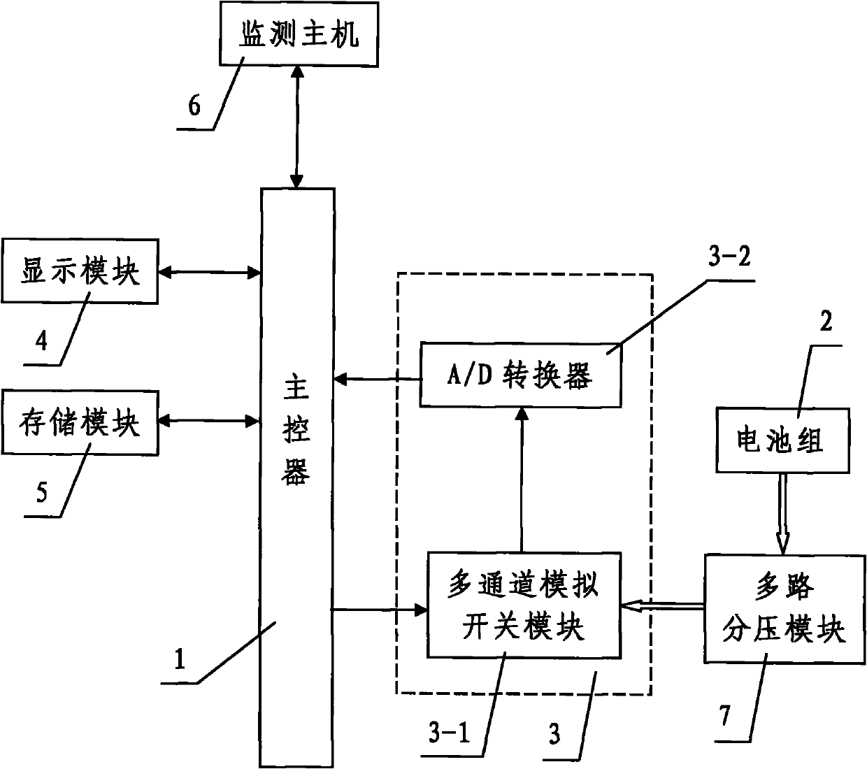
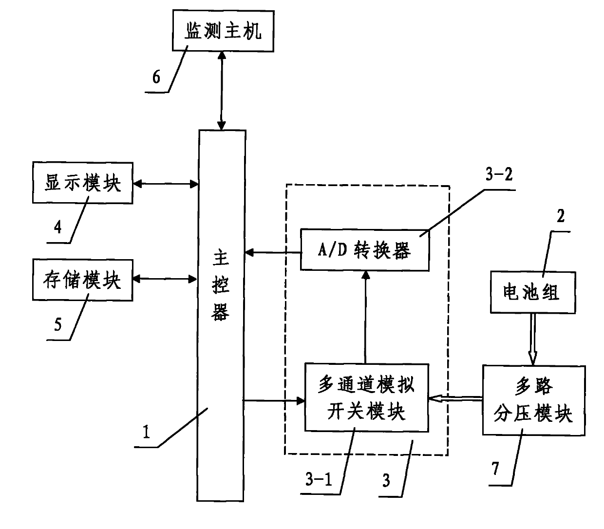
[0026] like figure 1 As shown, the present invention includes monitoring the host computer 6, detecting the overall discharge voltage of the battery pack 2 composed of a plurality of lithium batteries connected in series and in a discharging state and the respective single discharge voltages of the plurality of lithium batteries and storing the detected data Upload to the main controller 1 of the monitoring host 6, the multi-channel acquisition module 3 connected with the plurality of lithium batteries respectively, and the display module 4 and the storage module 5 respectively connected with the main controller 1, the main controller 1 is equipped with a voltage detection module that analyzes and processes the voltage signal collected by the multi-channel acquisition module 3 and obtains the overall discharge voltage value of the battery pack 2 and the individual discharge voltage values ​​of the plurality of lithium batteries. The multi-channel acquisition module 3 is connec...


PUM


Abstract

The invention discloses a multi-channel serially connected lithium battery detector. The detector comprises a monitor host machine, a master controller which is arranged for detecting an overall discharging voltage of a battery tank which comprises a plurality of lithium batteries and is in discharging state and uploading a detected data to the monitor host machine, a multi-channel collecting module connected with the lithium batteries, a display module and a storage module respectively connected with the master controller, wherein the master controller is provided with a voltage detection module; the multi-channel collecting module is connected with the master controller; and the multi-channel collecting module forms a multipath analog signal input passage between the lithium batteries and the master controller. The invention has the advantages of simple structure, convenient wiring, small volume, portability, a plurality of detection passages and excellent detecting property. The detector of the invention can efficiently detect the serially connected batteries, can meet the detection demand of high voltage and high precision, and can overcome the shortcomings of the current battery detector.

Description

technical field [0001] The invention relates to a battery tester, in particular to a multi-channel serial lithium battery tester. Background technique [0002] Currently, known battery testers include various types such as single battery testers and parallel battery testers. Among them, the battery tester of the single battery detection type can only test a single battery separately. Although it can perform real-time monitoring and display all test data synchronously, it is very troublesome once the entire battery pack needs to be measured. Although the battery tester of the parallel battery detection type can detect the entire battery pack at the same time, it can only detect the parallel type batteries, and cannot meet the high-voltage and high-precision measurement requirements. In addition, although it is possible to use an ordinary battery tester to test series batteries and meet the above high-voltage and high-precision measurement requirements, the required battery t...

Claims


Application Information

Patent Timeline
Patent Type & Authority Applications(China)
IPC IPC(8): G01R31/36
Inventor 李峰杨洪王一华王书会何显峰严学文
Owner XIAN SAFTY ENERGY TECH
Learn More