A multi-channel miniature electrical stimulator for sensory feedback in a prosthetic hand
An electrical stimulator, multi-channel technology, applied in the direction of prosthesis, medical science, artificial arm, etc., can solve the problems of lack of multiple feedback channels, poor reliability of sensory feedback, lack of general interfaces, etc., and achieve a high degree of interface generalization, Avoid charge accumulation, the effect of strong versatility
- Summary
- Abstract
- Description
- Claims
- Application Information
AI Technical Summary
Problems solved by technology
Method used
Image
Examples
specific Embodiment approach 1
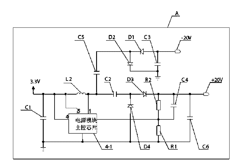
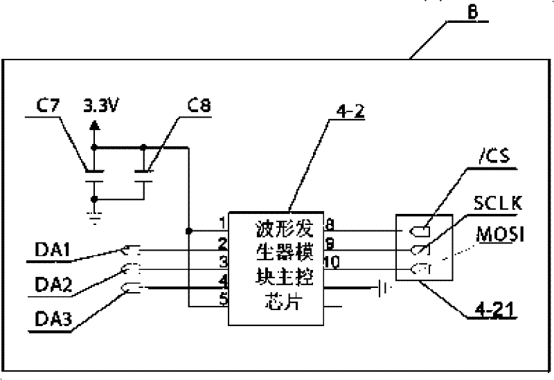
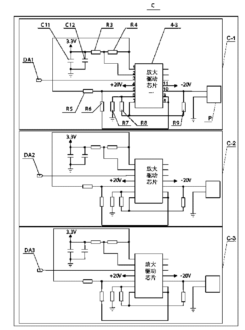
[0010] Specific implementation mode one: according to the instructions attached figure 2 and 3 Describe this embodiment in detail. This embodiment includes a power module circuit A, a waveform generator circuit B, and an amplifying drive circuit C. The +20V drive power output end of the power module circuit A is connected to the positive-phase drive power input of the amplifying drive circuit C. terminal, the -20V drive power output terminal of the power module circuit A is connected to the negative-phase drive power input terminal of the amplifying drive circuit C, the waveform output terminal of the waveform generator circuit B is connected to the waveform input terminal of the amplifying drive circuit C,
[0011] The amplifying driving circuit C includes three amplifying driving channels: the first amplifying driving channel C-1, the second amplifying driving channel C-2 and the third amplifying driving channel C-3, and each amplifying driving channel includes an amplifyin...
specific Embodiment approach 2
[0013] Specific implementation mode two: according to the instructions attached figure 1 Describe this embodiment in detail. This embodiment is a further description of Embodiment 1. The power module circuit A described in this embodiment includes: an inductor L2, a first rectifier diode D1, a second rectifier diode D2, a second rectifier diode Three rectifier diodes D3, fourth rectifier diode D4, first energy storage capacitor C2, second energy storage capacitor C5, first configuration resistor R1, second configuration resistor R2, positive feedback capacitor C4 and the main control of the power module The chip 4-1, the power supply input terminal of the main control chip 4-1 of the power module and the first terminal of the inductance L2 are connected to the 3.3V power supply, the second terminal of the inductance L2, the first terminal of the first energy storage capacitor C2 and the first terminal of the first energy storage capacitor C2 The first end of the second energy ...
specific Embodiment approach 3
[0014] Specific implementation mode three: according to the instructions attached figure 1 Describe this embodiment in detail. The difference between this embodiment and the first embodiment is that the power module circuit A also includes a first decoupling capacitor C1, a first output capacitor C6, and a second output capacitor C3. The first decoupling The two ends of the capacitor C1 are respectively connected to the 3.3V power supply and the power ground; The output terminal is connected to the power ground.
PUM
 Abstract
Description
Claims
Application Information
 - R&D Engineer
- R&D Manager
- IP Professional
- Industry Leading Data Capabilities
- Powerful AI technology
- Patent DNA Extraction
Browse by: Latest US Patents, China's latest patents, Technical Efficacy Thesaurus, Application Domain, Technology Topic, Popular Technical Reports.
© 2024 PatSnap. All rights reserved.Legal|Privacy policy|Modern Slavery Act Transparency Statement|Sitemap|About US| Contact US: help@patsnap.com


