Framework type track gauge and track direction measuring device

A technology of measuring device and gauge, which is applied in the directions of measuring device, transportation and packaging, adopting optical device, etc., can solve the problems such as the inability to detect the gauge and track direction at high speed, the safety hazard of the axle box gauge detection beam, etc., and meet the requirements of The demand for transportation safety and detection accuracy, and the effect of solving potential safety hazards

Inactive Publication Date: 2010-06-30
RAILWAY INFRASTRUCTURE TESTING RES INST CHINA ACAD OF RAILWAY SCI
View PDF0 Cites 42 Cited by
  • Summary
  • Abstract
  • Description
  • Claims
  • Application Information

AI Technical Summary

Problems solved by technology

[0004] The purpose of the present invention is to provide a frame-type gauge and track direction measuring device to solve the safety hazards of the axle box-type gauge detection beam itself and the problem that the gauge and track direction cannot be detected at high speeds. Provide testing equipment to provide technical support for the upgrade of the GJ-4 track inspection vehicle

Method used


Image

  • Framework type track gauge and track direction measuring device
  • Framework type track gauge and track direction measuring device
  • Framework type track gauge and track direction measuring device

Examples


Embodiment 1

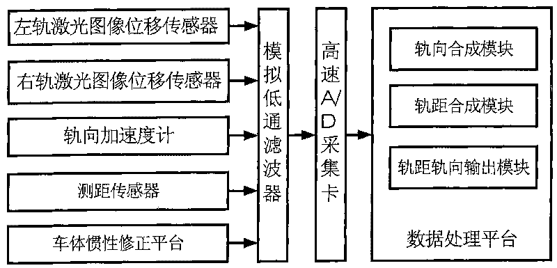
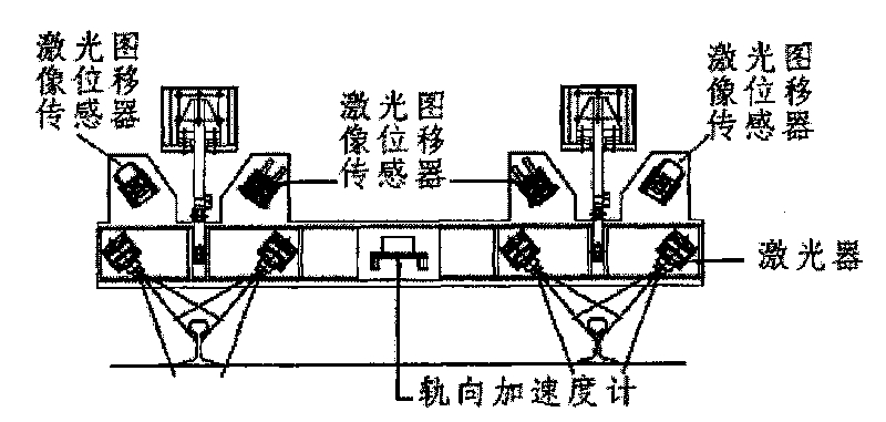
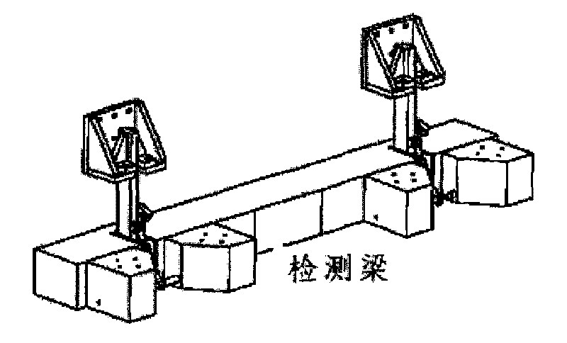
[0021] see Figure 1-Figure 3 ,in, figure 1 It is a structural schematic diagram of an embodiment of the frame gauge and track direction measuring device of the present invention, figure 2 It is a structural schematic diagram of an embodiment of the detection beam part of the frame gauge and track direction measuring device of the present invention, image 3 It is a schematic diagram of the appearance of the detection beam of the frame-type gauge and direction measuring device of the present invention.

[0022] This embodiment provides a framed gauge and track direction measuring device, which includes:

[0023] The detection beam is arranged under the track inspection vehicle perpendicular to the track; different from the prior art, the embodiment of the present invention sets the detection beam on the track inspection vehicle body in a framed manner, instead of the prior art track inspection vehicle On the rail axis, the vibration interference can be reduced.

[0024] T...

Embodiment 2

[0032] see again Figure 4 , Figure 4 It is the measuring principle diagram of the framework gauge and track direction measuring device of the present invention.

[0033] As shown in the figure, the left and right deviation of the track gauge is measured by laser image method, and the inertial measurement method is used for the track direction. The measurement principle of the track direction system is shown in Figure 4 .

[0034] For the definition of mutual positional relationship between the detection beam and the rail Figure 4 .

[0035] The output of the laser image measurement sensor mounted on the detection beam is as follows:

[0036] g L The displacement of the left gauge point relative to the detection beam (left gauge offset value);

[0037] g R The displacement of the right gauge point relative to the detection beam (right gauge offset value);

[0038] p L The displacement of the apex of the left rail surface relative to the detection beam (left high an...


PUM


Abstract

The invention provides a framework type track gauge and track direction measuring device, comprising a detection beam which is arranged on a track detector car framework; two groups of laser image displacement sensors which are respectively arranged at two ends of the detection beam for detecting the displacement of the track relative to the detection beam; a track direction accelerometer which is used for measuring the displacement of the central point of the detection beam relative to inertial space; a car body inertia correction platform which is used for measuring the posture of the detection beam and correcting the effect of the posture of the detection beam to the measurement data; a distance measurement sensor which is arranged at the countershaft end of a track detector car wheel for measuring the driving distance and driving speed of the track detector car and providing distance sampling time interval; and a data processing platform which is arranged on the detection car for processing the detection data to obtain the track gauge and the track direction detection results; the device solves the safety hidden troubles of an axle box track gauge detection beam and the problem that the track gauge and the track direction can not be measured under high speed.

Description

technical field [0001] The invention relates to a railway construction inspection device, in particular to a frame-type gauge and rail direction measuring device. Background technique [0002] The track inspection vehicle is a large-scale dynamic testing equipment developed to check track defects, eliminate hidden dangers of accidents, guide line maintenance and repair, improve track smoothness, and ensure driving safety. At present, the existing track inspection vehicles, such as the GJ-4 track inspection vehicle, are advanced in technology and accurate in measurement. They have been promoted and used in many railway bureaus, and they have played an important role in ensuring the safety of railway transportation and improving the stability and comfort of passenger trains. . However, the gauge and direction measurement adopts the gauge detection beam system installed on the axle box. With the continuous improvement of the railway running speed in my country, on the one hand...

Claims


Application Information

Patent Timeline
Patent Type & Authority Applications(China)
IPC IPC(8): B61K9/08G01B11/14B61D15/08
Inventor 任盛伟许贵阳
Owner RAILWAY INFRASTRUCTURE TESTING RES INST CHINA ACAD OF RAILWAY SCI
Why Eureka
Try Eureka