
Visual welding seam surface quality detection sensor based on line structure light

A technology for detecting sensors and weld surfaces, applied in the direction of optical testing flaws/defects, etc., can solve the problems of inability to detect the width of welds of equal-thickness butt plates, low cost, high price, etc., and achieves time-saving and labor-saving detection tasks. Low cost and the effect of improving the level of autonomy and intelligence

Inactive Publication Date: 2010-06-23
SHENYANG INST OF AUTOMATION - CHINESE ACAD OF SCI
View PDF0 Cites 61 Cited by
  • Summary
  • Abstract
  • Description
  • Claims
  • Application Information

AI Technical Summary

Problems solved by technology

A typical system that applies computer vision to weld surface quality inspection, such as the weld surface quality inspection system of Canada’s ServoRobot, uses the principle of structured light triangulation to identify weld quality. Since it can only obtain laser stripes that reflect the geometric outline of the weld, Therefore, it is not possible to detect the weld width of equal thickness butt joint plates
The weld surface quality inspection system of Switzerland Soutec company, the system can obtain laser stripes and weld surface grayscale images at the same time, but the price is more expensive
At present, a low-cost weld surface quality detection sensor that can obtain a grayscale image of the weld surface including laser stripes has not been reported.

Method used


Image

  • Visual welding seam surface quality detection sensor based on line structure light
  • Visual welding seam surface quality detection sensor based on line structure light
  • Visual welding seam surface quality detection sensor based on line structure light

Examples


Embodiment Construction

[0026] The present invention will be described in further detail below in conjunction with the accompanying drawings.

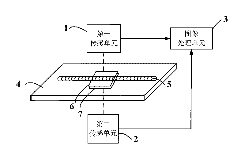
[0027] Such as figure 1 Shown is a schematic diagram of the composition of the welding seam quality detection sensor of the present invention, the sensor is composed of two sensing units (first to second sensing units 1 to 2) and an image processing unit 3 . The two sensing units are respectively located on both sides of the upper and lower surfaces of the weld 5 and are perpendicular to the two surfaces of the welding workpiece 4 . The sensing unit is electrically connected to the processing unit 3 .

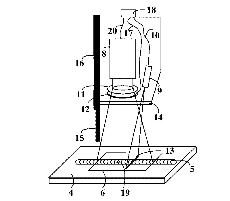
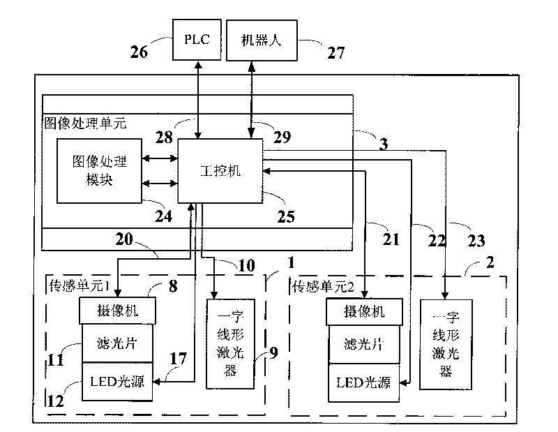
[0028] figure 2 It is a structural schematic diagram of the weld seam quality detection sensing unit of the present invention. The two sensing units have the same structure, and the structural description of one of the sensing units is taken as an example below. The sensing unit includes a camera 8, at least one inline laser 9, an LED ring light source 12...


PUM


Abstract

The invention discloses a visual welding seam surface quality real-time on-line detection sensor based on line structure light, comprising sensing units and an image processing unit, wherein two sensing units are respectively vertically installed at two sides of the upper and lower surfaces of the welding seam and connected with the image processing unit; the sensing units comprise a video camera for receiving the welding seam surface gray scale image including laser stripe formed on the welding work piece; a straight linear laser for generating laser structure light stripe on the welding work piece; an optical filter in front of the video camera lens; and an LED annular light source coaxially provided with the video camera and positioned in front of the optical filter. The invention uses the straight linear laser to project onto the upper and lower surfaces of the welding seam to generate the laser stripes; the camera collects the welding seam surface gray scale image including laser stripes to finally realize automatic quality detection of the upper and lower surfaces of the welding seam; and the precision of surface quality detection of the welding seam is improved. The sensor can be widely applied to the fields such as robot automatic welding.

Description

technical field [0001] The invention relates to the technical field of welding quality automatic detection, in particular to a sensor based on the principle of computer vision measurement, which acquires images of weld seams through visual sensors and uses image processing technology to identify defects in the surface quality of weld seams. The sensor can be widely used in robotic automatic welding and other fields. Background technique [0002] In the manufacturing industry, welding is the basis of many manufacturing methods. The quality of welding directly determines the reliability of products. Therefore, weld quality inspection is an important means to ensure welding quality, and has a wide demand in the field of welding. [0003] At present, the existing implementation schemes for weld quality inspection mainly include destructive inspection and non-destructive inspection. Among them, destructive inspections such as cupping, stretching, corrosion, and metallurgy have hi...

Claims


Application Information

Patent Timeline
IPC IPC(8): G01N21/88
Inventor 邹媛媛姜春英康永军许敏
Owner SHENYANG INST OF AUTOMATION - CHINESE ACAD OF SCI
Learn More