
Automatic enhanced fast start-up quartz oscillator

A technology of quartz oscillators and starters, applied in power oscillators, electrical components, etc., can solve the problems of shortening the start-up period, shortening the stabilization period, unstable oscillation frequency, etc., to achieve the effect of shortening the start-up period

Inactive Publication Date: 2010-06-16
UNIBAND ELECTRONICS CORP
View PDF0 Cites 2 Cited by
  • Summary
  • Abstract
  • Description
  • Claims
  • Application Information

AI Technical Summary

Problems solved by technology

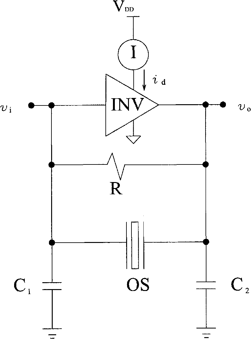
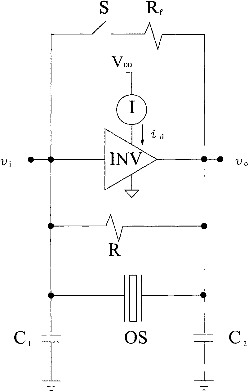
[0006] figure 1 and image 3 The oscillator circuits shown all require a two-stage current supply, and the jumping of the current will lead to instability of the oscillation frequency
in addition, image 3 Although the oscillator circuit shown shortens the start-up period, it does not contribute to shortening the stabilization period

Method used


Image

  • Automatic enhanced fast start-up quartz oscillator
  • Automatic enhanced fast start-up quartz oscillator
  • Automatic enhanced fast start-up quartz oscillator

Examples


Embodiment Construction

[0029] Figure 4a Shown is a circuit diagram of an example of the crystal oscillator of the present invention. The input terminal and the output terminal of the inverter INV are connected to two capacitors C 1 、C 2 After grounding, the resistor R and quartz OS are connected between the input terminal and the output terminal, and the high voltage terminal is connected to an external voltage source, and its voltage is recorded as V DD , a current source I is connected between the external voltage source and the high voltage terminal of the inverter INV, and the ground terminal is grounded.

[0030] The automatic booster circuit A-BOOSTER includes two detection terminals, a current compensation terminal, a receiving terminal and a grounding terminal. The receiving terminal is connected to a voltage source, and the grounding terminal is grounded. The voltage source is usually connected to the inverter INV external voltage source. The two detection terminals of the automatic bo...


PUM


Abstract

The invention provides an automatic enhanced fast start-up quartz oscillator, which is provided with an automatic enhanced circuit. The automatic enhanced circuit detects the voltages on the two sides of the quartz oscillator, adjusts the output enhanced current, rapidly shortens the start-up time and provides a stable current so as to effectively enhance the start-up efficiency and improve the situation of the second-stage current supply.

Description

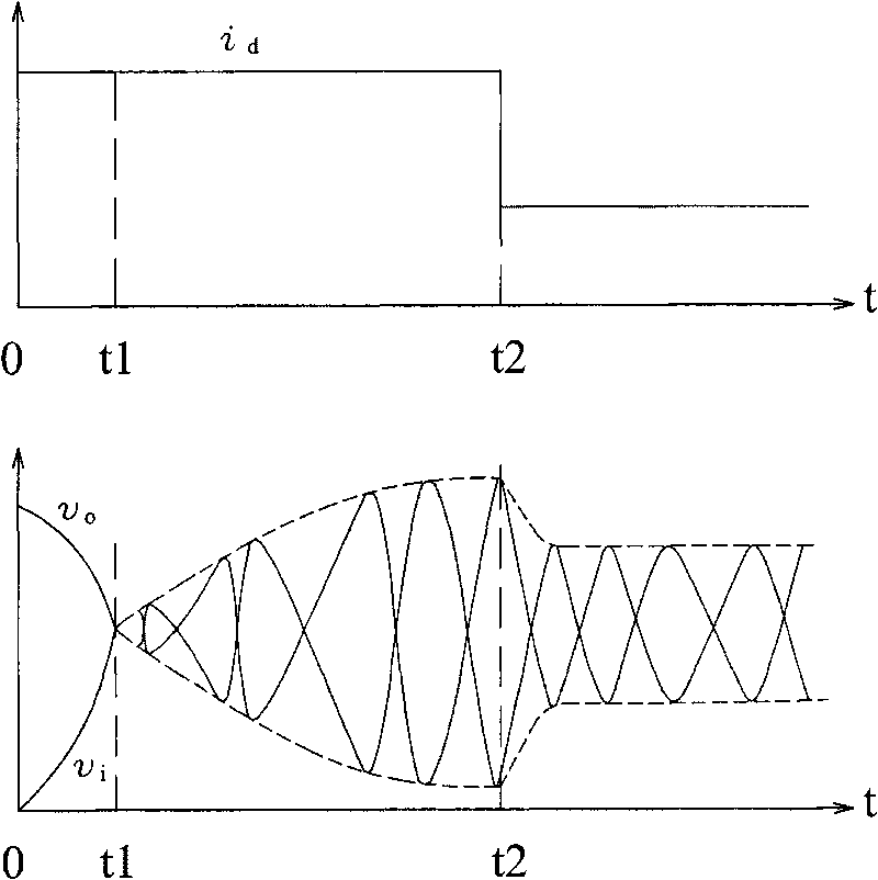
technical field [0001] The present invention relates to a quartz oscillator, in particular, it utilizes an auto-reinforcement loop to shorten the start time of oscillation. Background technique [0002] figure 1 Shown is a known oscillator circuit diagram, the two ends of the quartz OS are connected to the input and output of the inverter INV, and then respectively through two capacitors C 1 、C 2 ground, and a resistor R is connected between the input terminal and the output terminal of the inverter INV. The high voltage terminal and the ground terminal of the inverter INV are respectively connected to the external power supply I and the ground, and the power supply I supplies the current i of the inverter INV d . [0003] figure 2 Shown is the input current of a traditional inverter and the oscillation timing diagram of the oscillator to illustrate the operation of the oscillator. The voltages at the input and output of the inverter INV are V i with V o . at V i ...

Claims


Application Information

Patent Timeline
IPC IPC(8): H03B5/32H03B5/02H03B5/06
Inventor 陈政宏
Owner UNIBAND ELECTRONICS CORP
Learn More