
Light guide plate and backlight module

A light guide plate, light technology, applied in the direction of light guide, optics, optical components, etc., can solve the problems of processing limitation, uneven brightness, dark band distribution, etc., to achieve uniform brightness, reduce the phenomenon of alternating bright/dark bands, and reduce brightness The effect of unevenness

Active Publication Date: 2013-07-24
CORETRONIC
View PDF0 Cites 1 Cited by
  • Summary
  • Abstract
  • Description
  • Claims
  • Application Information

AI Technical Summary

Problems solved by technology

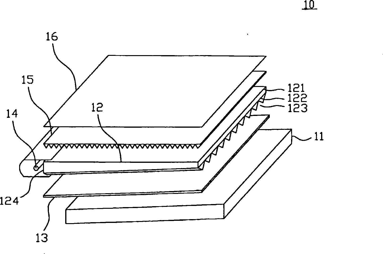
[0005] 2. The matte microstructure on the upper surface 121 of the existing backlight module 10 and the V-shaped groove 123 on the lower surface have obvious processing restrictions in order to match the reverse prism sheet 15 during manufacture.
[0006] 3. The side screen area of ​​the existing backlight module 10 close to the light source 14 usually has uneven brightness, especially when a point light source such as a light-emitting diode (LED) is used as the side light source, the side close to the light source 14 is prone to produce obvious contrast The phenomenon of V-shaped bright / dark band distribution

Method used


Image

  • Light guide plate and backlight module
  • Light guide plate and backlight module
  • Light guide plate and backlight module

Examples


Embodiment Construction

[0023] The aforementioned and other technical contents, features and effects of the present invention will be clearly presented in the following detailed description of the embodiments with reference to the figures. The directional terms mentioned in the following embodiments, such as: up, down, left, right, front or back, etc., are only referring to the directions of the drawings. Accordingly, the directional terms are used to illustrate and not to limit the invention.

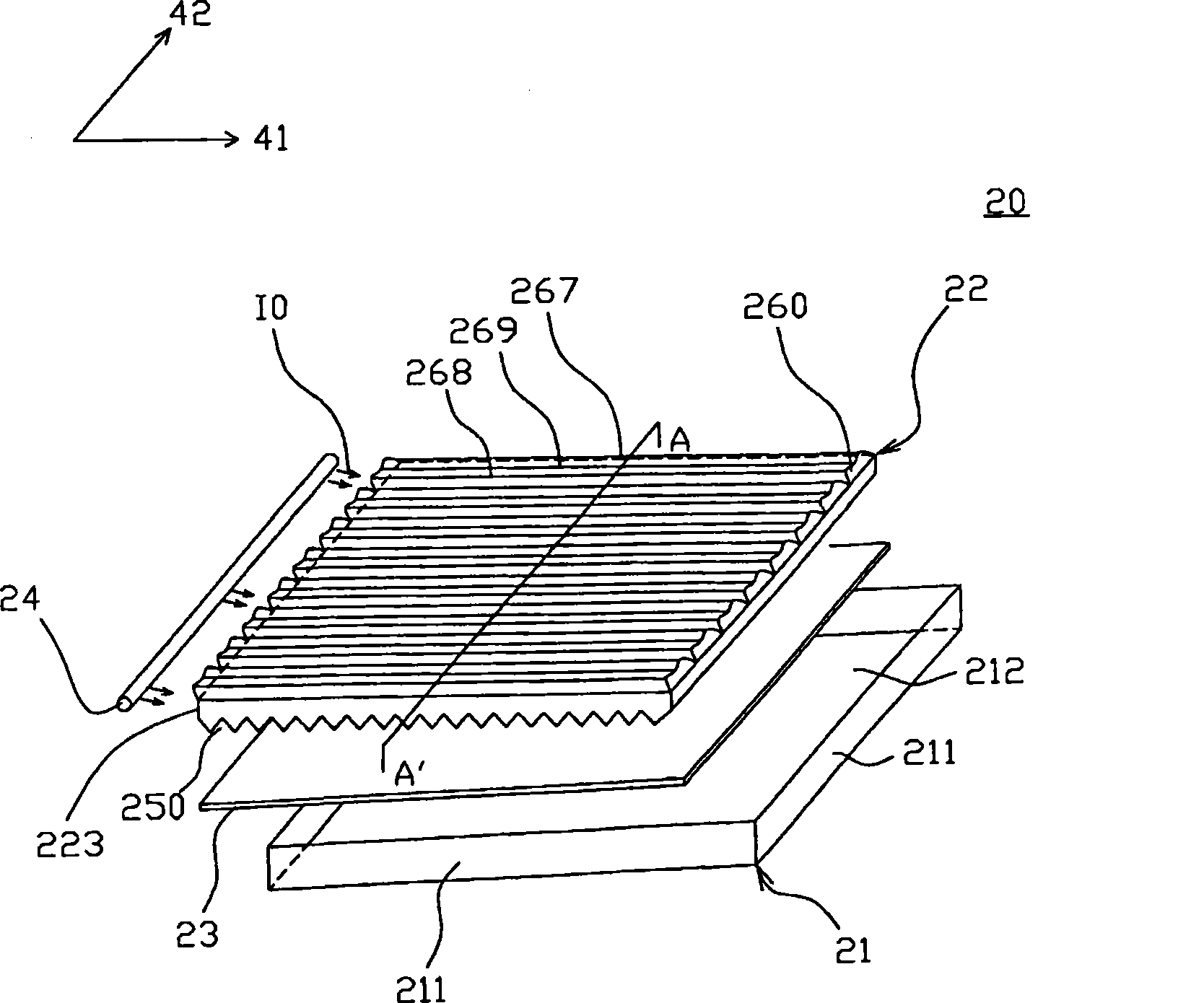
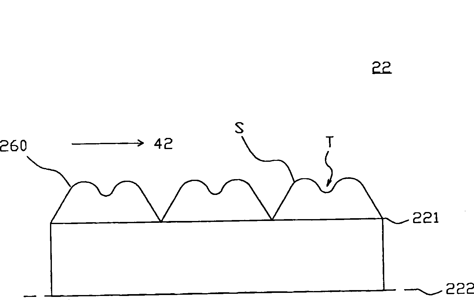
[0024] figure 2 In order to show a three-dimensional exploded view of a backlight module provided with a light guide plate according to an embodiment of the present invention, image 3 for display edge figure 2 The cross-sectional schematic diagram of the light guide plate on the line A-A'.

[0025] Please also refer to figure 2 and 3 , the backlight module 20 includes a backplane 21 , a light source 24 , a light guide plate 22 and a reflection sheet 23 . The backboard 21 has four sides 211 surrounding ...


PUM


Abstract

The invention discloses a light guide plate and a backlight module. The light guide plate is suitable for guiding the light to move along a first direction and comprises a first surface, a second surface, a light incident surface and a plurality of first cylindrical structures. The light incident surface is connected to the first surface and the second surface; and the light is emitted into the light guide plate from the light incident surface. The first cylindrical structures are arrayed on the first surface in a mode that respective long shaft directions are approximately parallel to the first direction. Each cylindrical structure is provided with a curved surface protruded relative to the first surface and at least one groove which extends and is distributed along the first direction is formed on the curved surface.

Description

technical field [0001] The invention relates to a light guide plate and a backlight module with the light guide plate. Background technique [0002] Please refer to FIG. 1 . FIG. 1 is an exploded perspective view of a conventional backlight module 10 . The backlight module 10 mainly includes a backplane 11; and a light guide plate (light guide plate, LGP) 12, a reflection sheet 13, a light source 14, a reverse prism sheet 15 and an optical film 16 arranged in the backplane 11 . The optical film 16 is adjacent to the light-emitting side of the reverse prism sheet 15, the reflection sheet 13 is adjacent to the lower surface 122 of the light guide plate 12, the light source 14 is arranged on the side light incident surface 124 of the light guide plate 12, and the light emitted by the light source 14 is from the side light incident surface 124 It is incident into the light guide plate 12 and exits from the upper surface 121 of the light guide plate 12 . A plurality of V-shape...

Claims


Application Information

Patent Timeline
Patent Type & Authority Patents(China)
IPC IPC(8): G02B6/00F21V8/00G02F1/13357
Inventor 张立典张良港郭浩然
Owner CORETRONIC
Learn More