
Display panel and display device

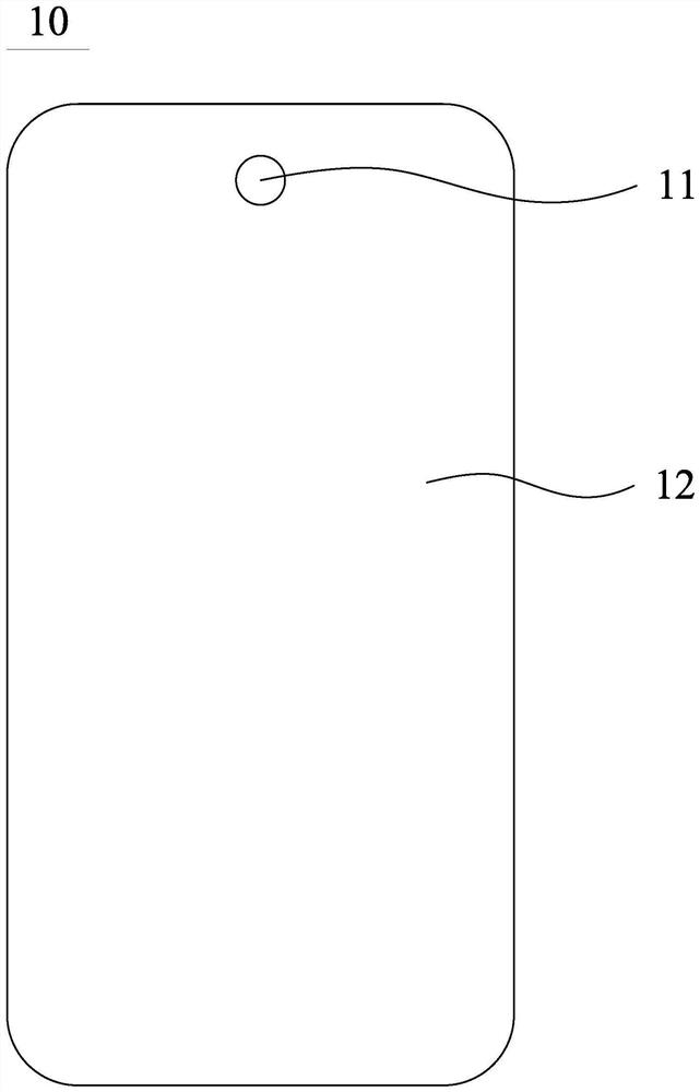
A display panel and display area technology, applied to semiconductor devices, electrical components, circuits, etc., can solve the problems of reducing the brightness uniformity of the display panel and uneven brightness at the boundary of the light-transmitting area

Active Publication Date: 2022-08-05
WUHAN CHINA STAR OPTOELECTRONICS SEMICON DISPLAY TECH CO LTD
View PDF6 Cites 0 Cited by
  • Summary
  • Abstract
  • Description
  • Claims
  • Application Information

AI Technical Summary

Problems solved by technology

[0003] However, due to the obvious cathode thickness difference between the light-transmitting area and the area outside the light-transmitting area, there is an obvious cathode step difference at the boundary of the light-transmitting area, resulting in obvious brightness unevenness at the boundary of the light-transmitting area, Reduced display panel brightness uniformity

Method used


Image

  • Display panel and display device
  • Display panel and display device
  • Display panel and display device

Examples


Embodiment Construction

[0032] The technical solutions in the embodiments of the present invention will be clearly and completely described below with reference to the accompanying drawings in the embodiments of the present invention. Obviously, the described embodiments are only a part of the embodiments of the present invention, but not all of the embodiments. Based on the embodiments of the present invention, all other embodiments obtained by those skilled in the art without creative efforts shall fall within the protection scope of the present invention. In addition, it should be understood that the specific embodiments described herein are only used to illustrate and explain the present invention, but not to limit the present invention. In the present invention, unless otherwise stated, the directional words such as "upper" and "lower" generally refer to the upper and lower parts of the device in actual use or working state, specifically the direction of the drawing in the accompanying drawings. ...


PUM

PropertyMeasurementUnit
thicknessaaaaaaaaaa

Abstract

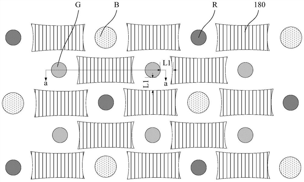
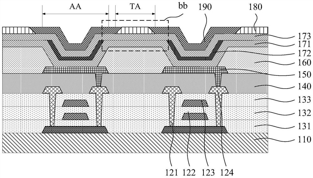
The invention discloses a display panel and a display device. The display panel includes a first display area and a second display area. The light transmittance of the first display area is greater than that of the second display area. In the first display area, The display panel includes a pixel area and a light-transmitting area located between the pixel areas. The display panel includes: a light-emitting unit layer; an auxiliary layer, including at least one auxiliary part, and the auxiliary part is located in the corresponding light-transmitting area; the first electrode layer is arranged in the on the light-emitting unit layer and the auxiliary layer; wherein, the auxiliary portion includes a platform portion and an edge portion located at the edge of the platform portion, the first electrode layer covers the light-emitting unit layer and at least part of the edge portion, and the thickness of the first electrode layer on the edge portion is less than The thickness of the first electrode layer on the light emitting unit layer. The invention ensures that the cathode step difference at the boundary of the light-transmitting area is reduced, the phenomenon of uneven brightness at the boundary of the light-transmitting area is reduced, and the brightness uniformity of the display panel is improved.

Description

technical field [0001] The present invention relates to the field of display, in particular to a display panel and a display device. Background technique [0002] In the existing under-screen camera display technology (Camera Under Panel, CUP), the display panel includes a first display area used for both display and shooting and a second display area only used for display, in order to improve the shooting effect of the camera , the cathode of the light-transmitting region in the first display region is usually removed to improve the light transmittance of the display panel in this region. [0003] However, due to the obvious difference in cathode thickness between the light-transmitting area and the area other than the light-transmitting area, there is an obvious cathode step difference at the boundary of the light-transmitting area, resulting in obvious brightness unevenness at the boundary of the light-transmitting area. Reduced display panel brightness uniformity. SUM...

Claims


Application Information

Patent Timeline
Patent Type & Authority Patents(China)
IPC IPC(8): H01L51/52H01L27/32
CPCH10K59/12H10K50/82H10K50/84
Inventor 金蒙吕磊袁涛黄金昌
Owner WUHAN CHINA STAR OPTOELECTRONICS SEMICON DISPLAY TECH CO LTD
Learn More