
A kind of backlight module and liquid crystal display device

A technology for a backlight module and a liquid crystal panel, which is applied to lighting devices, fixed lighting devices, cooling/heating devices of lighting devices, etc., can solve problems such as uneven brightness of a liquid crystal panel 110, and achieve the effect of reducing uneven brightness.

Active Publication Date: 2015-11-25
TCL CHINA STAR OPTOELECTRONICS TECH CO LTD
View PDF12 Cites 0 Cited by
  • Summary
  • Abstract
  • Description
  • Claims
  • Application Information

AI Technical Summary

Problems solved by technology

When the liquid crystal panel 110 is overheated, the phenomenon of uneven brightness (Thermal Mura) of the liquid crystal panel 110 is prone to occur.

Method used


Image

  • A kind of backlight module and liquid crystal display device
  • A kind of backlight module and liquid crystal display device
  • A kind of backlight module and liquid crystal display device

Examples


Embodiment Construction

[0015] The following description will be made in conjunction with the accompanying drawings and specific implementation manners.

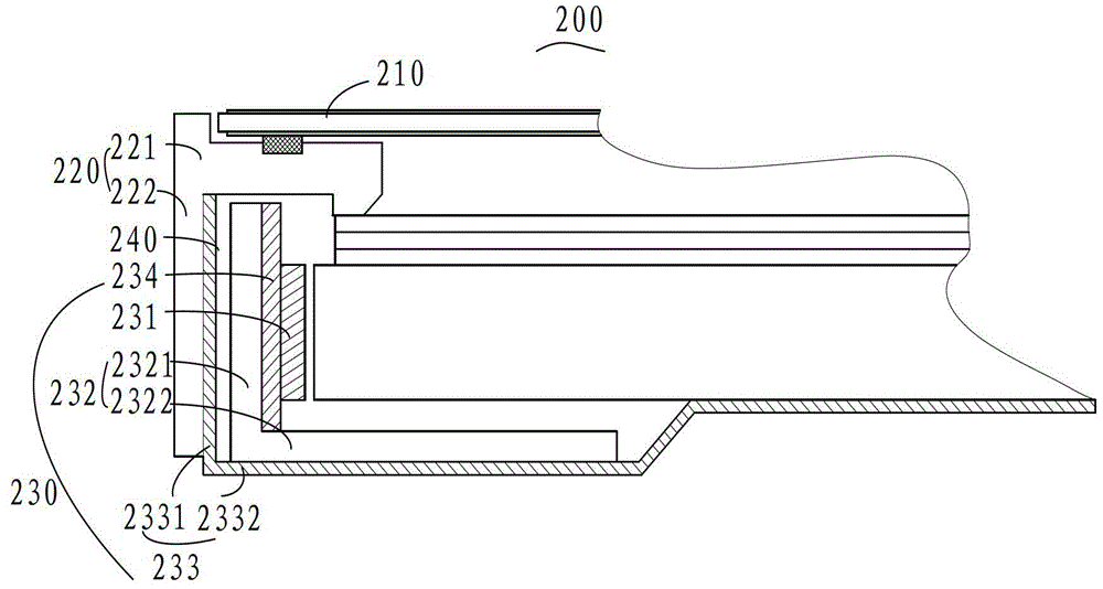
[0016] see figure 2 , figure 2 It is a partial structural schematic diagram of an embodiment of the liquid crystal display device of the present invention. In this embodiment, the liquid crystal display device 200 includes: a liquid crystal panel 210 , a middle frame 220 , a backlight module 230 and a heat blocking mechanism 240 .

[0017] The middle frame 220 includes a rectangular frame body 221 with a window in the middle and a first side plate 222 extending downward from the outside of the rectangular frame body 221 . The backlight module 230 includes a light source 231 , a heat conductor 232 , a backplane 233 and an MCPCB 234 . The back plate 233 includes a first bottom plate 2332 and a second side plate 2331 bent upward from the outer side of the first bottom plate 2332 . The heat conductor 232 includes a second bottom plate 2322 and a ...


PUM


Abstract

Provided are a backlight module (230) and a liquid crystal display device. The backlight module (230) comprises: a back plate (233), a heat source (231) and a heat obstruction mechanism (240). The heat source (231) is fixedly arranged with respect to the back plate (233), and the heat obstruction mechanism (240) is arranged in a heat transfer path between the back plate (233) and the heat source (231) to obstruct the heat which is transferred from the heat source (231) to the back plate (233). By providing the heat obstruction mechanism (240) in a heat transfer path of the heat source (231) and a liquid crystal panel (210), the heat of the heat source (231) is obstructed from being transferred to the liquid crystal panel (210), thereby reducing the phenomenon of light mura resulting from the overheating of the liquid crystal panel (210).

Description

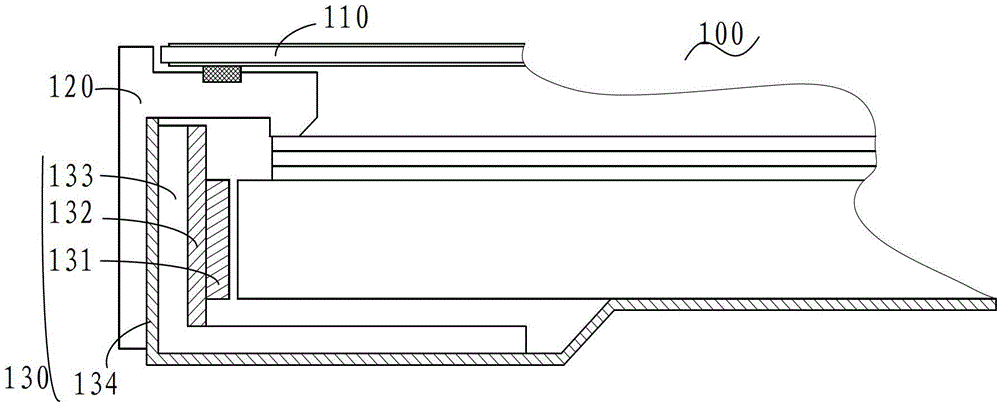
technical field [0001] The invention relates to the technical field of liquid crystal display, in particular to a backlight module and a liquid crystal display device. Background technique [0002] In the prior art, the structure of a liquid crystal display device is usually as follows figure 1 shown. The liquid crystal display device 100 includes a liquid crystal panel 110 , a plastic frame 120 and a backlight module 130 . Wherein, the plastic frame 120 is partially located between the liquid crystal panel 110 and the backlight module 130 . The backlight module 130 includes a backplane 134 , LEDs 131 , an aluminum extrusion 133 and a metal base printed circuit board (MCPCB) 132 . Wherein, a part of the aluminum extrusion 133 is located between the side plate of the back plate 134 and the MCPCB 132 , and is in direct contact with the inner surface of the side plate of the back plate 134 and the MCPCB 132 respectively. The plastic frame 120 is in direct contact with the o...

Claims


Application Information

Patent Timeline
Patent Type & Authority Patents(China)
IPC IPC(8): F21S8/00F21V29/71G02F1/13G02F1/13357
CPCG02B6/0085
Inventor 吴泽鑫
Owner TCL CHINA STAR OPTOELECTRONICS TECH CO LTD
Learn More