
Liquid absorbing core for embedded channels of heat pipe

A technology of fitting grooves and heat pipes, used in indirect heat exchangers, lighting and heating equipment, etc., can solve the problems of high heat source heating power, inability to meet heat dissipation requirements, and damage to system stability.

Inactive Publication Date: 2010-06-16
SOUTHEAST UNIV
View PDF0 Cites 9 Cited by
  • Summary
  • Abstract
  • Description
  • Claims
  • Application Information

AI Technical Summary

Problems solved by technology

[0004] In order to solve the problem that the heating power of the heat source is too large, and under the same limited heat source area, the maximum heat transfer capacity provided by the channel heat pipe cannot meet the heat dissipation requirements due to the limitation of its own structural conditions, thus destroying the stability of the system

Method used


Image

  • Liquid absorbing core for embedded channels of heat pipe
  • Liquid absorbing core for embedded channels of heat pipe
  • Liquid absorbing core for embedded channels of heat pipe

Examples


Embodiment Construction

[0047] Carry out further detailed description below in conjunction with accompanying drawing:

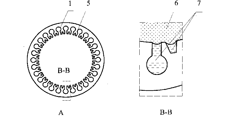
[0048] The working principle of the ordinary channel heat pipe is: in the evaporation section, the working liquid in the channel 1 absorbs the heat of the heat source and undergoes an evaporation phase change. The latent heat released after condensation in the condensation section is taken away by the cold source, and the working liquid flows from the condensation section to the evaporation section under the action of capillary force and gravity, and the condensate returned to the evaporation section evaporates again due to heat absorption, so that the heat source is continuously circulated. The heat is continuously transferred to the cold source. In the evaporation section, such as Figure 4 As shown, the gas-liquid interface can be divided into non-evaporating region, evaporating thin liquid film region and meniscus region. The working liquid evaporates at the entire gas-liquid i...


PUM


Abstract

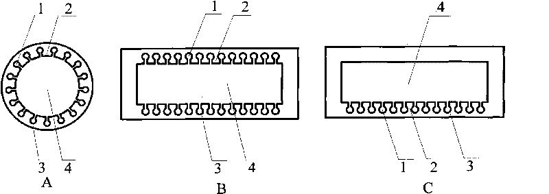
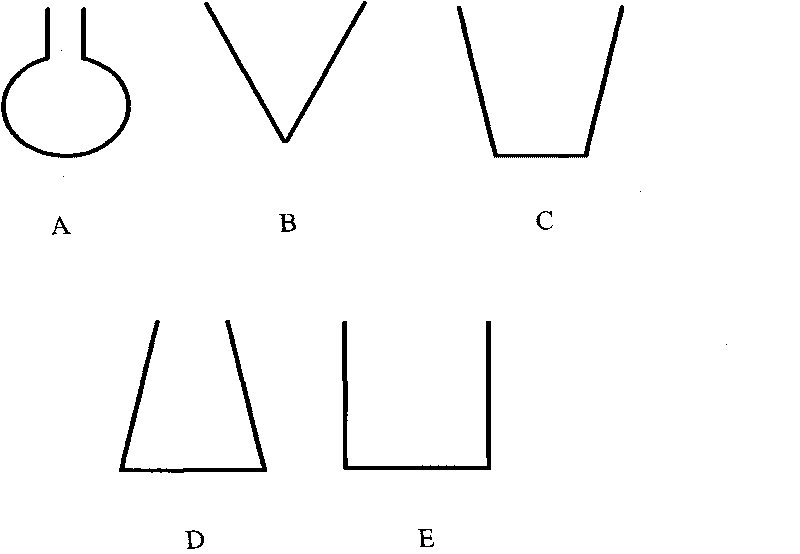
The invention discloses a liquid absorbing core for embedded channels of a heat pipe, which comprises a heat pipe wall, a steam chamber, common channels and ribs, wherein the common channels are arranged on the heat pipe wall; the common channels are separated by the ribs; embedded channels are formed on the ribs; the depth of each embedded channel is smaller than the depth of each common channel; and each embedded channel is in a triangular shape or an inverted trapezoidal shape. The novel capillary core heat pipe which has optimal combination of omega-shaped common channels and inverted trapezoidal or triangular embedded channels can eliminate the short circuit phenomenon so that the heat flow can smoothly reach an evaporative thin liquid film region to greatly increase the evaporative heat transfer area, thereby improving the heat transfer capacity of the heat pipe; and the space above the ribs among the common channels can be more effectively utilized to relieve the weight of the heat pipe. In addition, because gas-liquid interfaces can move inside and outside the channels freely, the liquid can be filled more conveniently and flexibly.

Description

technical field [0001] The invention relates to a heat dissipation device used in aviation thermal control systems, cooling of electronic components and heating, ventilating and air-conditioning systems, and can be widely used in non-pump, long-distance heat transport and transfer in civil systems. Background technique [0002] The principle of heat pipe technology is to use the evaporation and condensation of the working fluid to transfer heat. Since the latent heat generated by evaporation and condensation is quite large, the thermal conductivity of the heat pipe is hundreds of times that of the copper block. Axial channel heat pipes are among various types of heat pipes (sintered metal powder wick heat pipes, wire mesh wick heat pipes, dry channel type wick heat pipes, radial heat pipes, modulated wick heat pipes) with relatively simple processing and excellent heat transfer characteristics. Better heat pipes. At present, the power of electronic equipment is getting high...

Claims


Application Information

Patent Timeline
IPC IPC(8): F28D15/04
Inventor 陈永平朱旺法张程宾施明恒
Owner SOUTHEAST UNIV
Learn More