
Flat plate type heat pipe and manufacture method thereof

A technology of flat plate heat pipe and manufacturing method, which is applied to indirect heat exchangers, lighting and heating equipment, etc., can solve problems such as burning loss, capillary structure 102 drying, heat pipe burning loss, etc., and achieve the effect of ensuring heat transfer performance

Inactive Publication Date: 2010-06-16
FU ZHUN PRECISION IND SHENZHEN +1
View PDF0 Cites 4 Cited by
  • Summary
  • Abstract
  • Description
  • Claims
  • Application Information

AI Technical Summary

Problems solved by technology

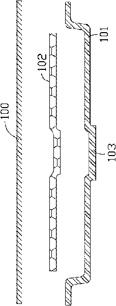
At this time, if the capillary structure 102 is too thick, the bubbles generated by the evaporation of the working liquid will form a vapor layer between the capillary structure 102 and the upper surface of the lower cover plate 101, thereby increasing the thermal resistance of the heat pipe, and causing the lower cover plate The temperature of 101 rises rapidly and causes the heat pipe to burn out
If the capillary structure 102 is too thin, the working liquid evaporates too fast and the condensed working liquid returns slowly, so that the capillary structure 102 is dried or even burned, thereby affecting the working performance of the heat pipe

Method used


Image

  • Flat plate type heat pipe and manufacture method thereof
  • Flat plate type heat pipe and manufacture method thereof
  • Flat plate type heat pipe and manufacture method thereof

Examples


Embodiment Construction

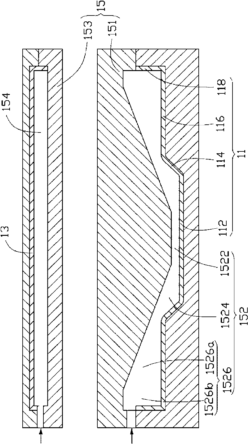
[0019] Such as image 3 and Figure 4 Shown is the flat heat pipe 10 according to the first embodiment of the present invention. The specific manufacturing process is as follows: (1) Provide a metal lower cover plate 11 and a concave, bowl-like shape that matches the lower cover plate 11 A flat metal upper cover plate 13, the lower cover plate 11 is made by stamping and arranged in a bowl shape, and has a horizontal heat absorption portion 112, and two extension portions inclined upward and outwardly extending from opposite ends of the heat absorption portion 112 114. Two joining portions 116 extending horizontally outward from the extension portion 114 and side walls 118 extending upward from the outer end of the joining portion 116; (2) providing a plurality of metal powders; (3) providing a mold 15 which includes An upper mold cover 153 with the upper cover plate 13 enclosed therein and one end opened, and a lower mold cover 151 with the lower cover plate 11 arranged therein ...


PUM


Abstract

The invention relates to a flat plate type heat pipe which comprises a lower cover plate, an upper cover plate and a capillary structure, wherein the upper cover plate is matched with the lower cover plate; the capillary structure is attached to the inner surface of the lower cover plate; the lower cover plate comprises a heat absorbing part which is in contact with a heat source and two extending parts which are upwards inclined and extend from two opposite ends of the heat absorbing part; the capillary structure comprises a first capillary section which is attached to the heat absorbing part of the lower cover plate and two second capillary sections which are attached to the extending parts of the lower cover plate; the thickness of the first capillary section is smaller than that of the second capillary sections, and the thickness of the second capillary sections decreases from the middle part to two opposite sides. The first capillary section of the first capillary structure of the flat plate type heat pipe is thinner than the second capillary sections; when the flat plate type heat pipe is used, the working liquid in the first capillary section can rapidly evaporate to carry the heat after the first capillary section absorbs the heat absorbed by the heat absorbing part of the lower cover plate; the working liquid stored in the second capillary sections can rapidly flow to the first capillary section, and the flat plate type heat pipe can not be burnt, thereby ensuring the heat transfer performance of the flat plate type heat pipe.

Description

Technical field [0001] The invention relates to a heat pipe and a manufacturing method thereof, in particular to a flat heat pipe and a manufacturing method thereof. Background technique [0002] At present, heat pipes are commonly used in the industry to solve the high-density heat dissipation problem of high-speed computers, such as heat pipes, loop heat pipes, and flat heat pipes (Vapor Chamber) products. [0003] The working principle of flat-plate heat pipes is the same as that of traditional heat pipes. Because it has a larger heat conduction area than traditional heat pipes, and meets the high practical value of "light, thin, short, and small", it is widely used in large heat dissipation areas. Electronic products. [0004] Such as figure 1 and figure 2 As shown, a general flat heat pipe has an upper cover plate 100 prepared by a stamping process, a lower cover plate 101 matched with the upper cover plate 100, and a capillary structure 102 between the upper cover plate 100 a...

Claims


Application Information

Patent Timeline
Patent Type & Authority Applications(China)
IPC IPC(8): F28D15/02B22F7/00
CPCB22F5/10F28D15/046F28D15/0233Y10T29/49353
Inventor 侯春树
Owner FU ZHUN PRECISION IND SHENZHEN
Learn More