Heat exchanger of air conditioner with double rows of pipelines

A double-row tube and heat exchanger technology, applied in evaporator/condenser, lighting and heating equipment, refrigeration components, etc., can solve the problems of low heat exchange efficiency, low energy efficiency, low heat exchange efficiency, etc., to improve Effect of heat transfer coefficient and heat transfer amount, improvement of heat transfer uniformity, and improvement of refrigeration energy efficiency

Inactive Publication Date: 2010-06-16
HISENSE HOME APPLIANCES GRP CO LTD +1
View PDF0 Cites 6 Cited by
  • Summary
  • Abstract
  • Description
  • Claims
  • Application Information

AI Technical Summary

Problems solved by technology

[0003] For the current household air conditioner split units, the outdoor unit often uses a heat exchanger with two or more rows of tubes, but the ordinary heat exchanger does not solve the problem of reverse heat exchange and does not have a good solution. Considering the influence of gravity, the reheating of the refrigerant and the short circuit of the air flow are not well avoided. Generally, the design of the heat exchanger adopts two parallel cross-flow flow arrangements. In this way, the heat transfer of the inner row is severely weakened, and the heat transfer efficiency is low. Although the heat transfer of the two refrigerants can be balanced by crossover, due to the , the two refrigerants are in a state of heat exchange that interferes with each other, and the temperature distribution of the two roads is uneven, which eventually leads to low overall heat transfer efficiency, or the energy efficiency is relatively high in one state of cooling / heating, and the energy efficiency in the other state On the low side, it is difficult to balance cooling / heating

Method used


Image

  • Heat exchanger of air conditioner with double rows of pipelines
  • Heat exchanger of air conditioner with double rows of pipelines
  • Heat exchanger of air conditioner with double rows of pipelines

Examples


Embodiment Construction

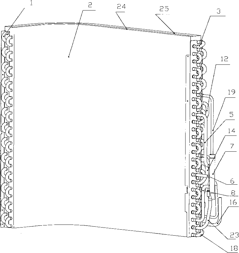
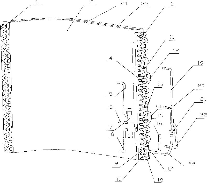
[0017] See attached Figure 1~3 , the double-row tube air-conditioning heat exchanger of the present invention includes fins 2 and double-row condensation pipes 1 passing through the inner cavity of the fins 2, a shunt pipe 7 and a distributor 21 connected to the condensation pipes 1 in the middle and lower parts of the fins 2 , and the connecting pipe 16 located at the bottom of the fin 2 and communicating with the condensing pipe 1, the condensing pipe 1, the shunt pipe 7 and the connecting pipe 16 all adopt copper pipes, and the distributor 21 is a full liquid copper distributor.

[0018] The branch pipe 7 includes the first branch pipe 5, the second branch pipe 6 and the third branch pipe 8 which divide the refrigerant into three paths, the first branch pipe 5 and the first inflow port of the condenser pipe 1 in the upper part of the fin 2 4, the second branch pipe 6 communicates with the second inflow port 15 of the condensation pipe 1 in the middle of the fin 2, and the ...


PUM

PropertyMeasurementUnit
Outer diameteraaaaaaaaaa

Abstract

The invention relates to the technical field of the heat exchanger of an air conditioner, which provides a heat exchanger of an air conditioner with double rows of pipelines with a novel refrigerant procedure. The heat exchanger can enhance the efficiency of heat exchange simultaneously during refrigeration and heating. The heat exchanger divides a refrigerant into three paths to flow into the heat exchanger, all the three paths of refrigerants flow from the inner row of the heat exchanger and finally flow out from the outer row of the heat exchanger, a reversed U type layout is adopted, and full-range countercurrent heat exchange is realized; the design of a three-path refrigerant procedure considers the influence of gravity, adopts an unequal-range flow path and enhances the uniformity of the heat exchange of each path during refrigeration, thereby enhancing the heat exchange coefficient and the heat exchange quantity; and the invention adopts an unequal diameter design for a convergence pipe of the three paths, enhances the uniformity of the heat exchange of refrigeration, also distributes the flow rate of the refrigerant for heating finely and enhances the heat exchange coefficient and the heat exchange quantity of heating. The heat exchange efficiency of the heat exchanger is enhanced by about 10% in comparison with an original heat exchanger, and finally, the refrigeration energy efficiency (EER) and the heating energy efficiency (COP) of the complete machine are enhanced.

Description

technical field [0001] The field of the invention relates to the technical field of air conditioners, in particular to the technical field of heat exchangers for air conditioners. Background technique [0002] At present, the energy saving of air conditioners has attracted more and more attention. In order to improve the efficiency of the air conditioner, the method of increasing the heat exchange area of ​​the heat exchanger is generally adopted, which increases the overall cost of the air conditioner. [0003] For the current household air conditioner split units, the outdoor unit often uses a heat exchanger with two or more rows of tubes, but the ordinary heat exchanger does not solve the problem of reverse heat exchange and does not have a good solution. Considering the influence of gravity, the reheating of the refrigerant and the short circuit of the air flow are not well avoided. Generally, the design of the heat exchanger adopts two parallel cross-flow flow arrangeme...

Claims


Application Information

Patent Timeline
IPC IPC(8): F25B39/00
Inventor 吕根贵
Owner HISENSE HOME APPLIANCES GRP CO LTD
Why Eureka
Try Eureka