
Bent-tube heating furnace

A bending tube heating and heating chamber technology, applied in the field of spiral energy-saving lamp manufacturing machinery, can solve the problems of slow temperature adjustment, difficult softening and adhesion of lamp tubes, uneven heating, etc., achieve fast cooling speed, avoid adverse effects, and increase production capacity Effect

Inactive Publication Date: 2010-06-16
浙江江山三友电子有限公司
View PDF0 Cites 1 Cited by
  • Summary
  • Abstract
  • Description
  • Claims
  • Application Information

AI Technical Summary

Problems solved by technology

The present invention utilizes graphite conduction heating to set the heating body and increase the insulation layer, the graphite layer is continuously distributed without gaps, the temperature distribution is more uniform, and the heat conduction speed and cooling speed of the graphite are fast, which is convenient to adjust to the adaptable temperature required for heating the glass tube element. It overcomes the defects of slow temperature adjustment and uneven heating caused by high-power electric furnace wires due to slow heat conduction and cooling speed, and can also avoid the adverse effects of broken electric furnace wires on production; the straight pipe is heated evenly in the heating tank and is not easy to produce stress. There are no hidden dangers of tube explosion and slow leakage defects caused by stress, and the lamp tube is not easy to soften and adhere to the furnace when heated at high temperature

Method used


Image

  • Bent-tube heating furnace
  • Bent-tube heating furnace
  • Bent-tube heating furnace

Examples


Embodiment Construction

[0016] The present invention will be further described below in conjunction with the accompanying drawings and specific embodiments.

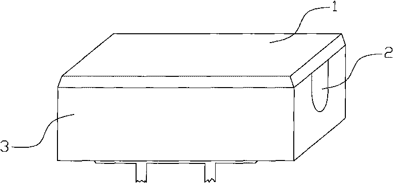
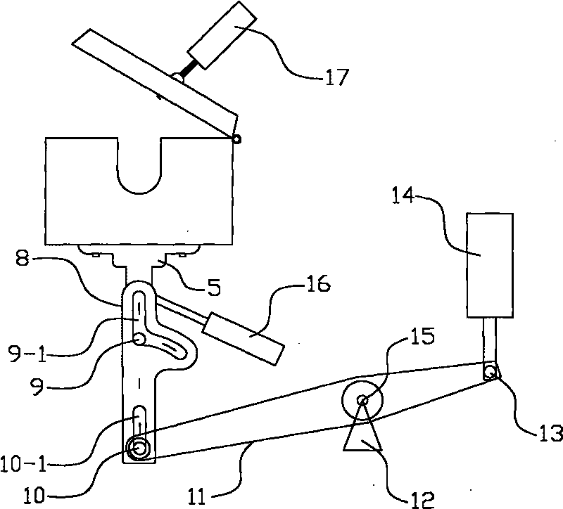
[0017] Elbow heating furnace such as Figure 1~2 As shown, it includes a double-layer structure with a furnace body 3 with a heating chamber. A furnace cover 1 is pivotally connected to the furnace body, and the furnace cover 1 is connected to a cover-opening cylinder 17 that can drive it to rotate around the shaft connection end 3-1. , the double-layer structure is a graphite layer 7 with a U-shaped cross-section and an insulating layer 6 of glass fiber material wrapped outside the graphite layer 7, and the heating chamber is a heating groove 2 formed by a U-shaped concave part of the graphite layer 7. Both ends of the heating tank are open. In addition, the present invention can also add the following technical features to make the bent pipe heating furnace more perfect.

[0018] Described body of furnace 3 is fixed on a base 5 with bolt 4,...


PUM


Abstract

The invention provides a bent-tube heating furnace for heating and softening when a straight tube is processed into a spiral tube by bending in energy-saving lamp manufacture. The conventional heating furnace has a heating wire structure, temperature distribution of a heating bath of the heating furnace is not uniform; the inside of the heated and softened straight tube easily generates stress, which has the defects of tube explosion and chronic gas leak; and the heating wire has difficult temperature control and high power consumption, and is easily burnt out if the heating wire is used continuously to affect production. The invention provides the bent-tube heating furnace with heating convenience, accurate temperature control, good production continuity and high yield aiming at the defects, which comprises a furnace body with a bilayer structure and a heating cavity, wherein the furnace body is coupled with a furnace cover; the bilayer structure is a graphite layer with a U-shaped section and an insulating layer coated outside the graphite layer; and the heating cavity is a heating groove which is formed by the U-shaped concave part of the graphite layer and is provided with twoopenings at two ends. By heating and softening the straight tube by the bent-tube furnace, the treated straight tube cannot easily generate stress in the tube so as to eliminate the hidden danger of tube explosion and chronic gas leak.

Description

【Technical field】 [0001] The invention relates to a spiral energy-saving lamp tube manufacturing machine, in particular to a bent tube heating furnace for heating and softening when a straight tube is bent and processed into a spiral tube. 【Background technique】 [0002] The structure of the existing heating furnace for energy-saving lamp tubes includes a furnace body with a cover. In the furnace body, refractory mud is used to set up electric furnace wires to form a heating tank with two ends open. The tube body of the straight tube is suspended in the heating tank and the furnace cover is covered, and the electric furnace wire is energized to heat and soften the straight tube. The electric furnace wire in this kind of heating furnace is coiled in a disc shape with gaps, so the temperature distribution in the heating tank is uneven. If the temperature is too high, the straight pipe will easily soften and stick to the furnace, and the overall uneven heating will cause stress...

Claims


Application Information

Patent Timeline
Patent Type & Authority Applications(China)
IPC IPC(8): C03B23/043C03B23/06H01J9/24
CPCY02P40/57
Inventor 姜伏波徐巨洪
Owner 浙江江山三友电子有限公司
Learn More