
Plastic corrugated pipe connecting device as well as molding method and molding device thereof

A technology of connecting device and forming device, which is applied in the direction of pipe connection arrangement, pipe/pipe joint/pipe fittings, tubular articles, etc., can solve the problems of reduced pipe production stability, large investment, and unacceptable users.

Active Publication Date: 2010-06-09
潍坊中云科研有限公司
View PDF1 Cites 5 Cited by
  • Summary
  • Abstract
  • Description
  • Claims
  • Application Information

AI Technical Summary

Problems solved by technology

The flaring is produced by synchronous online molding with the corrugated pipe production. Due to the structural requirements of the flaring, the extrusion speed and molding speed of the equipment must be adjusted every time a flare is produced. The production process is complicated and the stability of pipe production is reduced. ; At the same time, the length of the pipe with flare is limited, and the pipe with flare of any length cannot be provided according to the requirements. At the same time, because the flare is easily damaged during transportation and handling, it is easy to cause the entire pipe to be scrapped
The flaring of injection molding is difficult for users to accept due to the large investment, especially for large specifications (above 500mm).
In addition, there is also a method of connecting non-flare bellows by using split pipe connectors, but these methods all have some defects, such as a plastic bellows fast single piece mentioned in the patent No. 93201013.X The joint is to install a buckle on the hollow pipe body to connect the plastic bellows, which has a complex structure, high cost, and poor sealing performance

Method used


Image

  • Plastic corrugated pipe connecting device as well as molding method and molding device thereof
  • Plastic corrugated pipe connecting device as well as molding method and molding device thereof
  • Plastic corrugated pipe connecting device as well as molding method and molding device thereof

Examples


Embodiment Construction

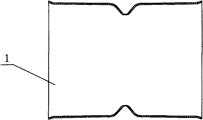
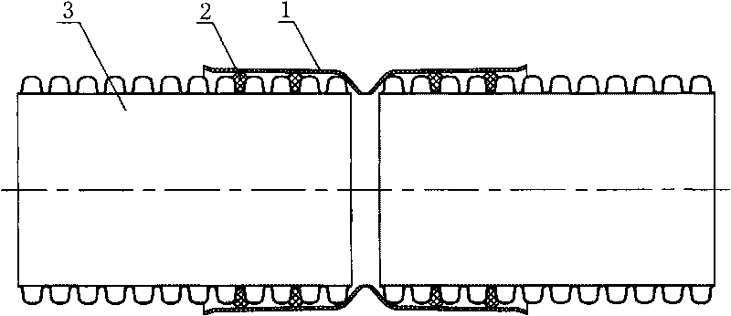
[0022] Such as figure 1 and figure 2 As shown, the plastic corrugated pipe connection device 1 is used to connect the plastic corrugated pipe 3 without flare. An inwardly recessed positioning portion is provided at the middle portion corresponding to the seam of the bellows. The pipes on both sides of the pipe body are respectively bell-shaped, and the two ends of the pipe body are respectively provided with flared openings for the insertion of bellows. A seal ring 2 is embedded in the wave groove at the joint end of the bellows. After the bellows is inserted into the bellows connecting device 1, the seal ring 2 is closely attached to the bell-shaped pipe.

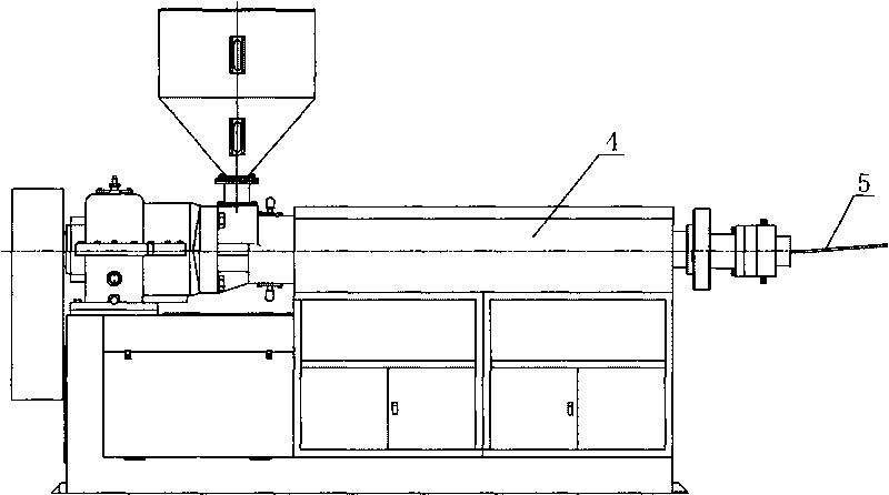
[0023] The molding method of the plastic corrugated pipe connection device is to extrude the plastic strip 5 through the extruder 4. The cross section of the plastic strip 5 is flat, and the plastic strip 5 is wound on the forming mandrel by a winding machine 6. 7, and multiple layers are wound on the forming mandrel 7...


PUM


Abstract

The invention discloses a plastic corrugated pipe connecting device. A pipe connecting device is a revolution body solid wall pipe body which is sleeved at the periphery of the joint end of two corrugated pipes, and an inwards concave positioning part is arranged in the middle of the pipe body and corresponds to a joint position of the corrugated pipes. The invention also discloses a molding method of the plastic corrugated pipe connecting device. A plastic belt material is extruded by an extruder, wound on a molding core die by a winding machine and tightly pressed by a belt material pressing device in the winding process; and after being cooled by a cooling device, the plastic corrugated pipe connecting device is molded. The invention also discloses a molding device of the plastic corrugated pipe connecting device, which comprises the extruder and the winding machine, wherein the winding machine comprises the rotatable molding core die; and the belt material pressing device is arranged outside the molding core die and connected with the cooling device. The plastic corrugated pipe connecting device has the advantages of simple structure, convenient processing and reliable function. The molding method has the advantage of reasonable process. The molding device has the advantages of high production efficiency and low cost.

Description

technical field [0001] The invention relates to a pipe connector of a plastic corrugated pipe, and also relates to a molding method and a molding device of the pipe connector. Background technique [0002] At present, there are two ways to connect plastic corrugated pipes and plastic corrugated pipes: 1. Connect by elastic sealing and plugging; 2. Connect by hot-melt welding. The most commonly used is to use elastic sealing plug-in connection. The expansion molding of this connection method includes synchronous online molding with the production of corrugated pipes and injection molding with injection machines and special molds. The flaring is produced by synchronous online molding with the corrugated pipe production. Due to the structural requirements of the flaring, the extrusion speed and molding speed of the equipment must be adjusted every time a flare is produced. The production process is complicated and the stability of pipe production is reduced. At the same time, ...

Claims


Application Information

Patent Timeline
IPC IPC(8): F16L47/06B29D23/00
Inventor 张泽奎韩炳强王培森
Owner 潍坊中云科研有限公司
Learn More