
Thin-wall pressure water pipe

A technology for water transmission pipelines and pipelines, which is used in pipeline laying and maintenance, pipes/pipe joints/fittings, machinery and equipment, etc. It can solve the problems of large-area land inundation loss, high engineering cost, leakage, etc., and reduce construction costs. And the difficulty of installation, the effect of reducing project cost and saving pipe wall materials

Inactive Publication Date: 2010-06-09
黄国宏
View PDF0 Cites 5 Cited by
  • Summary
  • Abstract
  • Description
  • Claims
  • Application Information

AI Technical Summary

Problems solved by technology

The disadvantages of pressurized or non-pressurized water diversion tunnels are high engineering cost, difficult construction, and long construction period. In the case of poor geological conditions, there will be landslides and water leakage in the tunnel
[0007] Due to the above reasons, the cost of water diversion facilities in diversion hydropower projects often accounts for a large proportion of the total cost, and there are always hidden dangers of accidents that cannot be eradicated, resulting in heavy losses after accidents
Moreover, the hydropower resources suitable for the construction of water diversion channels and aqueducts have been basically developed, and in areas where water diversion channels and aqueducts cannot be built in the horizontal direction, the construction of dams will cause large areas of land inundation loss
Therefore, the abundant hydropower resources in this region have not been able to be effectively developed and utilized for a long time

Method used


Image

  • Thin-wall pressure water pipe
  • Thin-wall pressure water pipe
  • Thin-wall pressure water pipe

Examples


Embodiment Construction

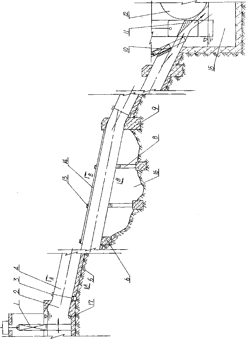
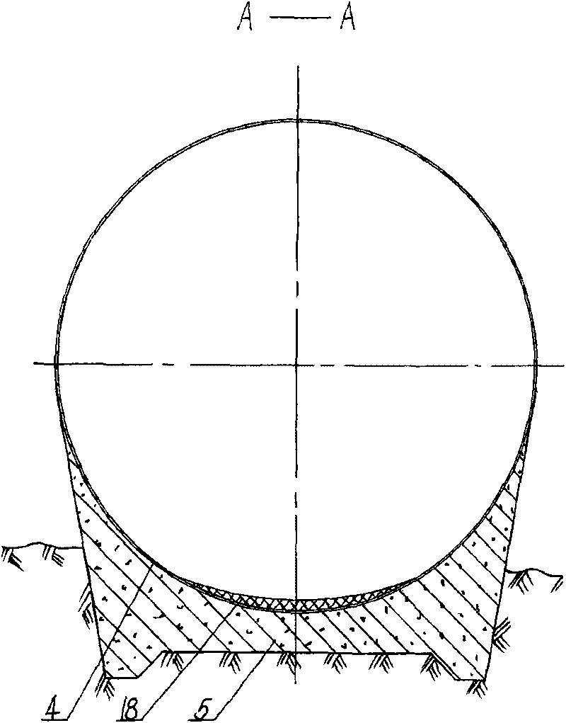
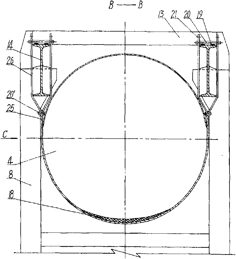
[0039] figure 1 , figure 2 , image 3 with Figure 4 A first embodiment of the invention is shown. This embodiment describes in detail the overall arrangement structure and operation process of using the thin-walled pressure water pipeline to deliver pressure water flow to the impact water turbine.

[0040] Such as figure 1 with figure 2 Shown: Concrete tube bed 5 buried half height below the ground is laid along the surface of the ground. The bottom surface of the tube bed 5 is in the shape of a plane with toothed walls, while the top surface is in the shape of a circular arc with a diameter of 2 meters. groove. A thin-walled pressure pipe 4 with a diameter of 2 meters and a diameter of 2 meters made of a 3 mm thick ordinary steel plate is laid in the arc-shaped groove, and an anti-wear layer 18 of epoxy mortar is provided on the bottom surface of the pipe 4 .

[0041] Such as figure 1 , image 3 with Figure 4 As shown: there are ravines 16 on the ground surface,...


PUM


Abstract

The invention relates to a thin-wall pressure water pipe that conveys pressure flow to a water turbine for hydroelectric generation, in particular to a large-scale thin-wall pressure water pipe. The water pipe mainly consists of a pipeline, a pipe bed or a support beam for supporting the pipeline, a support member arranged between the support beam and the pipeline and the like. Due to the superior loading condition, simple and reasonable structure, convenient and accessible manufacturing, mounting and constructing of the water pipe, the wall of the pipe is thin and the cost is low. The whole water pipe is safe and highly reliable with less on-way waterhead loss, thereby meeting water conveying request for large-flow pressure flow.

Description

Technical field [0001] The thin-walled pressure water delivery pipeline relates to a thin-walled water delivery pipeline for delivering pressurized water flow to a hydroelectric turbine, in particular to a large thin-walled pressure water delivery pipeline. Background technique [0002] At present, the composition of water diversion facilities that deliver large flow of water to the water turbines of diversion-type hydroelectric power generation is as follows: the water diversion channel arranged in the horizontal direction and the water transfer aqueduct connected with the water diversion channel and continued to be arranged in the horizontal direction form a certain After the drop, the water flow is input into the turbine by the pressure pipe arranged in a short distance and a large slope. Its shortcomings are: [0003] In the water diversion channel in the prior art, due to the wide floor area, the leakage loss of water in the channel is serious. Moreover, in order to f...

Claims


Application Information

Patent Timeline
Patent Type & Authority Applications(China)
IPC IPC(8): F16L1/00
Inventor 黄国宏
Owner 黄国宏
Learn More