Electric integrated energy-saving power device

A power device and electrical technology, applied to engine components, machines/engines, non-variable engines, etc., can solve the problems of small input-output ratio, slow effect, long cycle, etc., to achieve high input-output ratio and effective Fast, short cycle effect

Inactive Publication Date: 2010-06-09
刘林章
View PDF0 Cites 0 Cited by
  • Summary
  • Abstract
  • Description
  • Claims
  • Application Information

AI Technical Summary

Problems solved by technology

Moreover, the above-mentioned energy development requires a certain scale of facilities, which requires large investment, long cycle, slow effect, and small input-output ratio.

Method used


Image

  • Electric integrated energy-saving power device
  • Electric integrated energy-saving power device
  • Electric integrated energy-saving power device

Examples


Embodiment 1

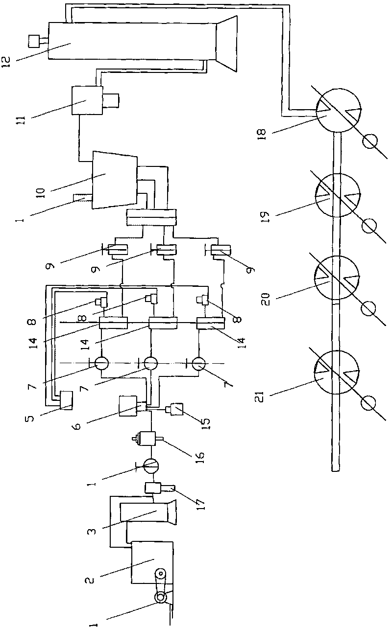
[0013] An electrical integrated energy-saving power device, such as figure 1 As shown, it includes: a motor 1, an air compressor 2, a cooler 10, a cylinder 14, and a control valve. The motor 1 drives the air compressor 2 through a transmission mechanism, and the air outlet pipe of the air compressor 2 communicates with the gas tank 3, The gas tank 3 is connected to the oil mist device 16 through the water separator 17 and the pressure control valve 4. The oil mist device 16 passes through the direction control valve 6 and the flow control valve 7 to the cylinder 14, and the air outlet pipe of the cylinder 14 passes through the shut-off valve 9 and passes through the cooler 10. The oil-water separator 11 to the atmospheric tank 12, the outlet pipe of the atmospheric tank 12 is connected to the inlet pipe of the first energy-saving environmental protection device 18, the outlet pipe of the first energy-saving environmental protection device 18 is connected to the inlet pipe of the ...

Embodiment 2

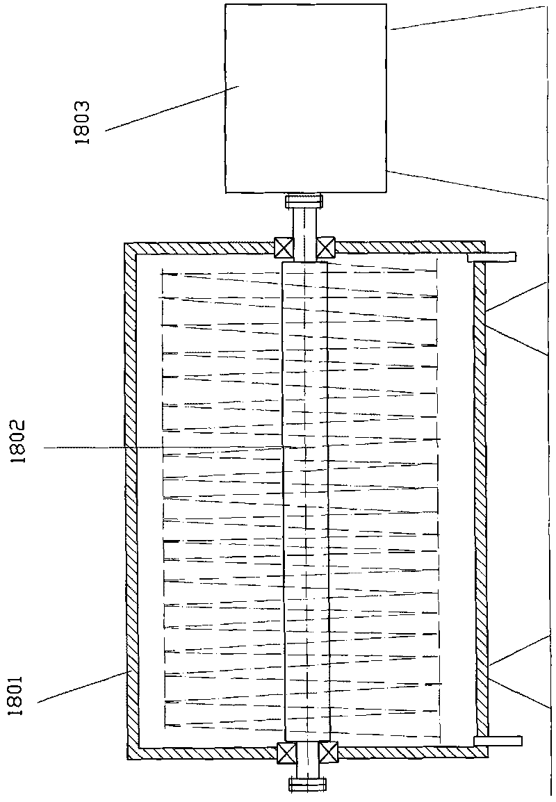
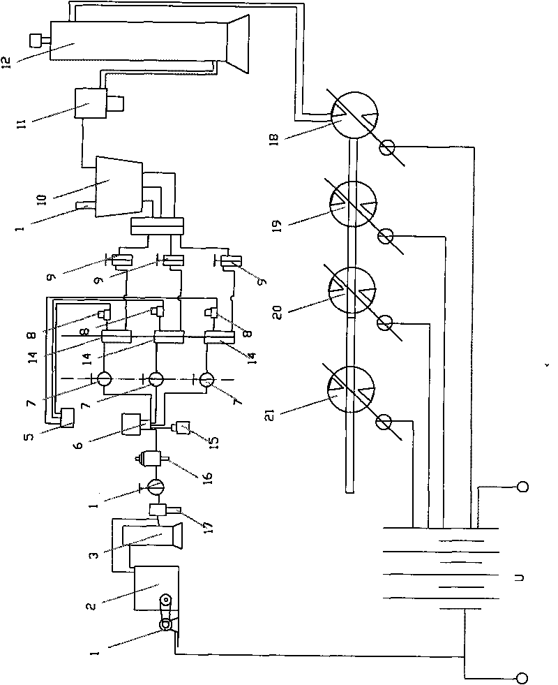
[0019] Electrically integrated energy-saving power devices for generating sets, such as image 3 As shown, the structure is basically the same as that of Embodiment 1, except that the magnetic shaft 1802 of the energy-saving environmental protection device is connected to the power shaft of the generator 1803. So as to form a generator set, the more energy-saving and environmental protection devices, the more power generation. A small part of the electric energy generated by the generator set is supplied to the electric motor 1, and most of it is integrated into the power grid.

[0020] In the experiment: the motor 1 uses 7, 5 kW / h; the air compressor 2 uses 1, 3M 3 / Min; The air tank 3 uses ATBC with a volume of 2, 5M 3 The pressure control valve 4 uses 8-10 atmospheres; the logic element 5 uses PT3 / 8; the directional control valve 6 uses the AG type; the flow control valve 7 uses ARX20; the cooler 10 adopts fin type KAM5; the oil-water separator 11 adopts AM650; the cylinder 1...


PUM


Abstract

The invention relates to an electric integrated energy-saving power device which comprises an electromotor, an air compressor, a cooler and a cylinder, and is characterized in that the air compressor is driven by the electromotor through a driving mechanism, the air outlet pipe of the air compressor is communicated with an air tank, the air tank is communicated with an oil atomizer through a water-separating gas filter and a pressure control valve, the oil atomizer is connected with the cylinder through a direction control valve and a flow control valve, the air outlet pipe of the cylinder is connected with an atmosphere tank through a stop valve, the cooler and a water oil separator, at least one air outlet pipe of the atmosphere tank is communicated with the air inlet pipe of at least one first energy-saving and environment-friendly device, the air outlet pipe of the first energy-saving and environment-friendly device is communicated with the air inlet pipe of a second energy-saving and environment-friendly device, the air outlet pipe of the second energy-saving and environment-friendly device is communicated with the air inlet pipe of a third energy-saving and environment-friendly device, i.e. the air outlet pipe of the previous energy-saving and environment-friendly device is communicated with the air inlet pipe of the next energy-saving and environment-friendly device, and the magnetic axes of the energy-saving and environment-friendly devices are connected with an engine power shaft. The device uses air as an energy source and has the advantages of little investment, short period, rapid effect taking and high input-output ratio.

Description

Technical field [0001] The invention relates to a power generation device using compressed air, in particular to an electrical integrated energy-saving power device. Background technique [0002] The power currently used generally comes from electric, wind, hydro, thermal and atomic energy, which require a certain energy source and a certain reserve. At present, my country and the world have limited energy reserves and need to further develop new energy. Moreover, the facilities required for the above-mentioned energy development must have a certain scale, with large investment, long cycle, slow results, and low input-output ratio. Summary of the invention [0003] The purpose of the present invention is: in order to overcome the above shortcomings, to provide an electrical integrated energy-saving power device, which uses air as an energy source, which is an inexhaustible and inexhaustible energy source. At the same time, it has a small investment and a short cycle. The advantag...

Claims


Application Information

Patent Timeline
Patent Type & Authority Applications(China)
IPC IPC(8): F01D1/00F01D9/00F01D5/02
Inventor 刘林章
Owner 刘林章
Why Eureka
Try Eureka