
Blast-furnace vent device

A technique of stabbing tuyeres and blast furnaces, applied in tuyeres and other directions to achieve the effect of high power and high efficiency

Inactive Publication Date: 2010-06-09
NANTONG BAOSTEEL IRON & STEEL CO LTD
View PDF0 Cites 3 Cited by
  • Summary
  • Abstract
  • Description
  • Claims
  • Application Information

AI Technical Summary

Problems solved by technology

[0006] The technical problem to be solved by the present invention is to provide a blast furnace tuyere device to solve the problems of safety and effectiveness in blast furnace blasting in the prior art

Method used


Image

  • Blast-furnace vent device
  • Blast-furnace vent device
  • Blast-furnace vent device

Examples


Embodiment 1

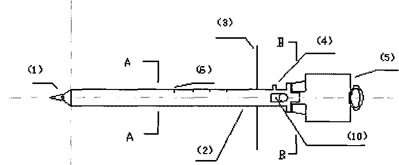
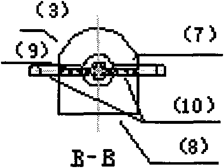
[0023] like figure 1 , figure 2 and image 3 As shown, a blast furnace tuyere device includes a cone head 1, a hollow steel pipe 2, a protective plate 3, a compressed air interface 4, an air hammer 5, a transparent plexiglass window 7, an iron plate 8, a screw 9 and an inverted rod 10, There are 4 holes on the cone head 1, the head of the hollow steel pipe 2 is welded to the cone head 1, the inside is connected with 0.6Mpa compressed air, the middle and rear part is provided with a protective plate 3, the upper part is Transparent plexiglass window 7, the lower half is iron plate 8.

[0024] The compressed air enters through the compressed air interface 4 arranged at the rear of the hollow steel pipe 2, and is connected by a detachable hose.

[0025] The tail of the hollow steel pipe 2 is connected to the detachable air hammer 5 , and the inverted rod 10 is vertically inserted into the front of the air hammer 5 and the hollow steel pipe 2 and fixed by screws 9 .

[0026] ...


PUM


Abstract

The invention relates to a blast-furnace vent device which comprises a conical head (1), a hollow steel tube (2), a protection plate (3), a compressed air interface (4), an air hammer (5), a transparent organic glass window (7), an iron plate (8), screws (9) and a reverse knockout rod (10), wherein a hole is arranged on the conical head (1), the head of the hollow steel tube (2) is welded with the conical head (1) and internally introduced with compressed air, the protection plate (3) is arranged at the middle-rear part of the hollow steel tube (2), the transparent organic glass window (7) is arranged at the upper-half part of the hollow steel tube (2), and the iron plate (8) is arranged at the lower-half part of the hollow steel tube (2); the compressed air enters through the compressed air interface (4) arranged at the rear part of the hollow steel tube (2); the tail part of the hollow steel tube (2) is connected with the air hammer (5), the reverse knockout rod (10) is uprightly inserted into the front part of the air hammer (5) and the hollow steel tube (2) and fixed by the screws (9); and scale marks (6) are marked on the surface of the hollow steel tube (2). The invention can solve the problems of the security and the effectiveness in the venting process of a blast furnace.

Description

technical field [0001] The invention belongs to the field of ironmaking blast furnace equipment, and in particular relates to a tuyere device for blast furnaces. Background technique [0002] Due to production needs, blast furnaces often have tuyeres blocked and poked. Existing poke tuyere technology is to use solid iron rod (or hollow oxygen tube) as poke tuyere bar, the defect that this method exists is: [0003] 1. When the tuyere is poked, the high-temperature debris in the furnace and the hot air at about 1250°C will be sprayed out, which is easy to burn the operator. [0004] 2. The efficiency of poking the tuyere is low. When poking the tuyeres, many people need to hold the iron rods for poking the tuyeres at the same time. If manual poking is used, the tuyeres cannot be opened due to insufficient strength or improper coordination, which takes time and effort and affects the production of the blast furnace. [0005] 3. When the tuyere is poked, the iron rod contact...

Claims


Application Information

Patent Timeline
Patent Type & Authority Applications(China)
IPC IPC(8): C21B7/16
Inventor 张永亮彭坤宋俊殷晓伟沈火明
Owner NANTONG BAOSTEEL IRON & STEEL CO LTD
Learn More