High-torque dual-rotor stress-type longitudinal-torsion composite ultrasonic motor and its electric excitation method

An ultrasonic motor and double-rotor technology, applied in the direction of generator/motor, piezoelectric effect/electrostrictive or magnetostrictive motor, electrical components, etc., can solve the problem of limiting motor output torque, complex motor processing technology, lifting, etc. question

Inactive Publication Date: 2011-11-30
JIANGSU FENGKE ULTRASONIC MOTORS TECH
View PDF0 Cites 0 Cited by
  • Summary
  • Abstract
  • Description
  • Claims
  • Application Information

AI Technical Summary

Problems solved by technology

However, the general longitudinal-torsion composite ultrasonic motor adopts a sandwich structure to play the role of longitudinal vibration piezoelectric ceramics, which has a low utilization rate for longitudinal vibration piezoelectric ceramics.
In 1998, Ueha developed a dual-rotor longitudinal-torsion composite ultrasonic motor, which can effectively use the vibration of the longitudinal-vibration piezoelectric ceramic sheet, but the disadvantages are: first, a part of the longitudinal-vibration piezoelectric ceramic sheet is placed on the rotor The above structure makes this kind of motor must add brush structure to work, and the processing technology of the motor is complicated; secondly, because the contact occurs between the piezoelectric ceramic sheets, the manufacture of the friction pair becomes complicated and difficult
These all limit the further improvement of the motor output torque

Method used


Image

  • High-torque dual-rotor stress-type longitudinal-torsion composite ultrasonic motor and its electric excitation method
  • High-torque dual-rotor stress-type longitudinal-torsion composite ultrasonic motor and its electric excitation method
  • High-torque dual-rotor stress-type longitudinal-torsion composite ultrasonic motor and its electric excitation method

Examples


Embodiment Construction

[0017] Below in conjunction with accompanying drawing, the technical scheme of invention is described in detail:

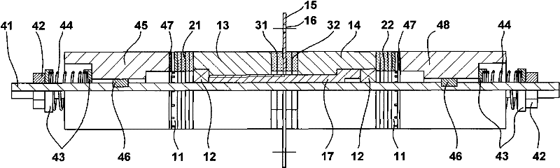
[0018] In the present invention, the large-torque dual-rotor stress-type longitudinal-torsion composite ultrasonic motor is as follows: figure 1 As shown, including stator assembly and rotor assembly. The stator assembly consists of friction plates 11, the first group of longitudinal vibration piezoelectric ceramics 21, the first counterweight 13, the first group of torsional vibration piezoelectric ceramics 31, the flange 15, the second group of torsional vibration piezoelectric ceramics 32, the first Two counterweights 14, the second group of longitudinal vibration piezoelectric ceramic sheets 22, fastening bolts 17 and two radial bearings 12; the rotor assembly consists of a rotating shaft 41, a lock nut 42, a spring cover 43, a spring 44, and A rotor 45, a key 46, a friction material 47, and a second rotor 48 are formed. First, the first counterweight 13, th...


PUM


Abstract

The invention discloses a high-torque double-rotor stress-type longitudinal-torsion compound ultrasonic motor and an electric excitation method, which belong to the technical field of ultrasonic motors. The motor of the invention includes a stator assembly and a rotor assembly. The stator assembly consists of friction plates, a first set of longitudinal Vibrating piezoelectric ceramics, first counterweight, first group of torsional vibration piezoelectric ceramics, flange, second group of torsional vibration piezoelectric ceramics, second counterweight, second group of longitudinal vibration piezoelectric ceramics, fastening Bolts and two radial bearings; the rotor assembly is composed of a rotating shaft, a lock nut, a spring cover, a spring, a first rotor, a key, a friction material, and a second rotor. The method of the present invention utilizes the first-order torsional vibration in the stator and the second-order longitudinal vibration in the motor as a whole, and the longitudinal vibration piezoelectric ceramic is placed near the contact surface of the stator and the rotor, that is, at the nodal plane of the longitudinal vibration, to fully excite and apply the motor longitudinal vibration. Compared with the background technology, the present invention has a larger locked-rotor torque.

Description

technical field [0001] The invention belongs to the technical field of ultrasonic motors, and in particular relates to a high-torque double-rotor stress type longitudinal-torsion compound ultrasonic motor. Background technique [0002] Ultrasonic motor is a new type of power output device that utilizes the inverse piezoelectric effect of piezoelectric ceramics and ultrasonic vibration. Compared with electromagnetic motors, it has the advantages of compact structure, high torque at low speed, fast response (millisecond level), self-locking when power is off, good position and speed control, no electromagnetic interference, and low-noise operation. Longitudinal-twisting composite ultrasonic motor is a major category of ultrasonic motors. The research on it can be traced back to the late 1980s. Up to now, there are no less than dozens of types of structures. The longitudinal-twisting composite ultrasonic motor usually contains two vibrators—a longitudinal vibrator and a torsio...

Claims


Application Information

Patent Timeline
Patent Type & Authority Patents(China)
IPC IPC(8): H02N2/10
Inventor 赵淳生杨淋
Owner JIANGSU FENGKE ULTRASONIC MOTORS TECH
Why Eureka
Try Eureka