
Image display device

A technology for image display and lighting devices, applied in projection devices, installation, photography, etc., can solve problems such as abnormal color of projected images and decreased illuminance, and achieve the effect of suppressing abnormal colors or decreased illuminance

Active Publication Date: 2010-05-26
SANYO ELECTRIC CO LTD
View PDF2 Cites 1 Cited by
  • Summary
  • Abstract
  • Description
  • Claims
  • Application Information

AI Technical Summary

Problems solved by technology

In this way, after transportation, even if the first lamp is turned on, the inclination angle of the reflector becomes inappropriate, and as a result, there are problems of abnormal color and lowered illuminance in the projected image.

Method used


Image

  • Image display device
  • Image display device
  • Image display device

Examples


Embodiment Construction

[0048] Hereinafter, the configuration of the projector according to the embodiment will be described with reference to the drawings.

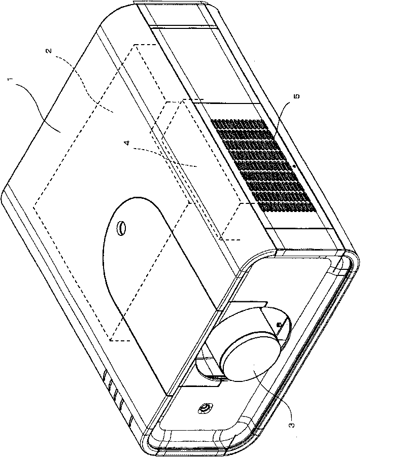
[0049] figure 1 It is a diagram (perspective view of the exterior) showing the structure of the projector. The projector has a casing 1 . The casing 1 has a roughly rectangular parallelepiped shape with thin top and bottom and long front and rear, and an air inlet 5 for introducing outside air into the inside of the casing 1 is formed on a side surface thereof.

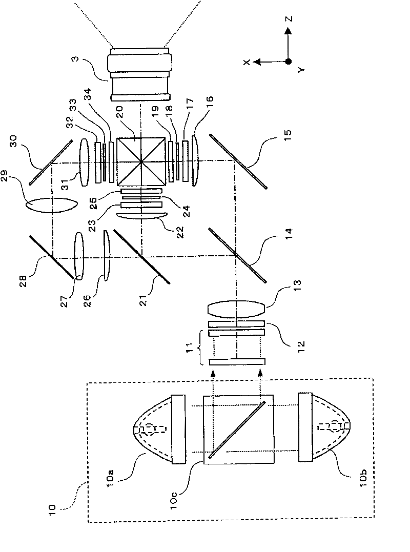
[0050] An optical engine (engine) 2 , a projection lens 3 , and a cooling device 4 are disposed in the housing 1 . The optical engine 2 generates light (video light) modulated according to a video signal. A projection lens 3 is installed in the optical engine 2 , and the front portion of the projection lens 3 is exposed from the front of the housing 1 . The video light generated by the optical engine 2 is projected through the projection lens 3 onto a screen arranged in front of th...


PUM


Abstract

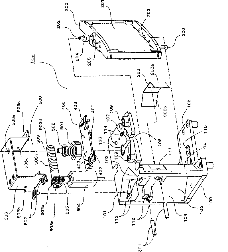
The invention provides an image display device. When a light source is started, a reflector is positioned at the preset rotation position at high accuracy and abnormal color or reduced illuminance generated in a projection image is smoothly controlled. In the case where the lamp A is used, the mirror is temporarily driven in the direction of lamp B before the lamp A is activated. Thereafter, the mirror is returned to the position where the lamp A is used, and is pressed against a restraining member. Thereby, the mirror is positioned at a proper angle with respect to the light from the lamp A when the lamp A is activated.

Description

technical field [0001] The invention relates to an image display device, which is especially suitable for an image display device with multiple light sources. Background technique [0002] Currently, a projection type video display device (hereinafter, referred to as a "projector") that projects an enlarged image on a screen has been commercialized and widely used. In such projectors, a lamp is generally used as a light source, and the light from the lamp is modulated by a light modulating element and then projected on a screen. [0003] At this time, if the lamp breaks during the projection operation, image display is interrupted. In order to avoid such inconveniences, there have been proposed projectors in which two lamps are arranged in advance, and the remaining lamp is used when the lamp in use breaks down (for example, Patent Documents 1 and 2). [0004] In this structure, two lamps are arranged to face each other, and a reflector unit is arranged between these lamps...

Claims


Application Information

Patent Timeline
IPC IPC(8): G03B21/20G02B7/182
CPCH04N9/3197G03B21/2066G03B21/2013G03B21/2093H04N9/3191H04N9/3155G03B33/12G03B21/145G03B21/20H04N9/3164
Inventor 吉村太一神原稔昌
Owner SANYO ELECTRIC CO LTD
Learn More