
Underlay-board-equipped input device

An input device and pad technology, applied in the input/output process of data processing, instruments, electrical and digital data processing, etc. rigid effect

Inactive Publication Date: 2013-02-06
NITTO DENKO CORP
View PDF0 Cites 3 Cited by
  • Summary
  • Abstract
  • Description
  • Claims
  • Application Information

AI Technical Summary

Problems solved by technology

[0005] However, during the writing process, if there is a relative misalignment between the optical position detection device and the paper, the position of the characters written on the paper (analog data) and the position of the characters displayed on the display (digital data) ) becomes inconsistent (deviation between analog and digital data)
In addition, if the writing to the paper is temporarily interrupted and the paper is taken out from the optical position detection device, and then the paper is placed under the optical position detection device again for writing again, the position of the paper will be different from that of the previous paper. generate dislocation
If you write on the paper in this state, you can write on the paper without misalignment, but a misalignment (discrepancy between analog data and digital data) will still be displayed on the display.

Method used


Image

  • Underlay-board-equipped input device
  • Underlay-board-equipped input device
  • Underlay-board-equipped input device

Examples


Embodiment 1)

[0105] (making pads)

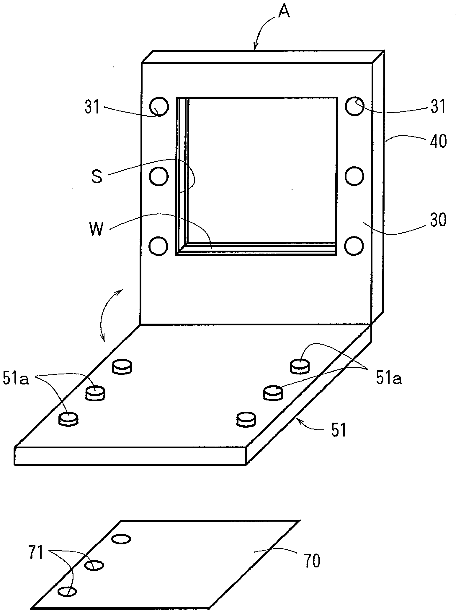
[0106] An aluminum plate was prepared as a material for forming the backing plate, and the aluminum plate was cut to produce figure 1 Shown is a backing plate formed with a plurality of cylindrical protrusions. The outer diameter of the protrusion is 5 mm, and the height is 5 mm.

[0107] (Material for forming the lower cladding layer)

[0108] Component A: 75 parts by weight of epoxy resin containing alicyclic skeleton (produced by Daicel Chemical Industry, Japan, EHPE3150).

[0109] Component B: 25 parts by weight of epoxy group-containing acrylic polymer (manufactured by NOF (NOF Corporation), MAIPNOIFG-0150M).

[0110] Component C: 4 parts by weight of a photoacid generator (manufactured by Sunafro Co., Ltd., CPI-200K).

[0111] The material for forming the under cladding layer was prepared by dissolving the above components A to C in cyclohexanone (solvent) together with 5 parts by weight of an ultraviolet absorber (manufactured by Chiba Japan C...

Embodiment 2)

[0133] (making an input device)

[0134] Form the same quadrangular frame-shaped holding plate as in the above-mentioned embodiment 1, and arrange a plurality of light-emitting diodes (produced by Sharp Corporation, GL4800E0000F) side by side on one of the opposite sides of the periphery of the hollow part for input. A plurality of photodiodes (manufactured by Sharp, PD411PI2E00P) are arranged side by side on the other of the two opposing sides of the periphery of the hollow portion. In addition, similarly to the above-mentioned Example 1, a CMOS driver CPU, a quartz resonator, a wireless module, two coin-shaped lithium batteries, etc. were mounted on a circuit board to manufacture a control part, and the control part was fixed on the above-mentioned holding plate. . Here, the aforementioned light-emitting diodes, photodiodes, and control components are covered with a rectangular frame-shaped stainless steel protection plate (thickness: 0.5mm) to obtain Figure 18 input devi...


PUM

PropertyMeasurementUnit
Outer diameteraaaaaaaaaa
Heightaaaaaaaaaa

Abstract

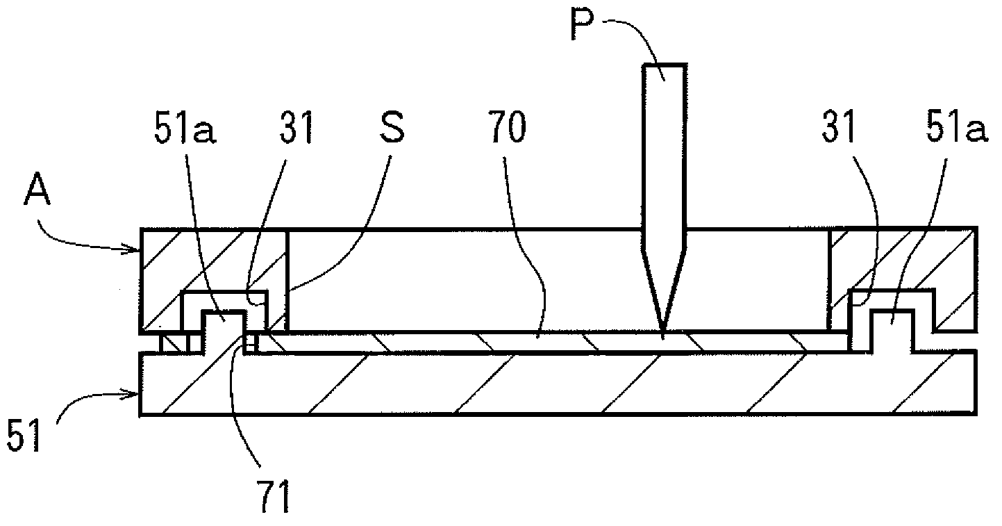
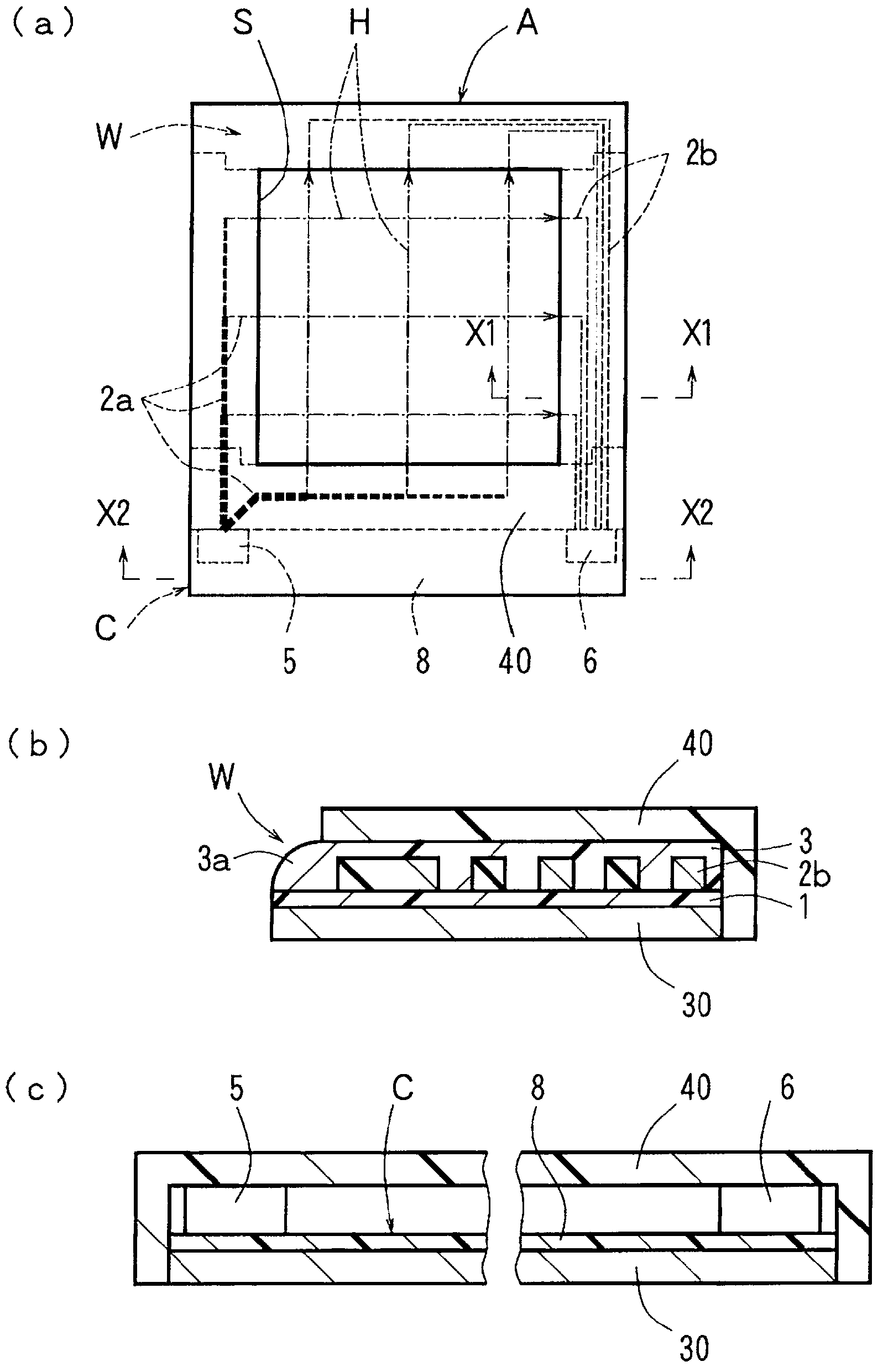
An underlay-board-equipped input device is provided which is capable of preventing positional displacement of a writing paper sheet when a user is writing on the set writing paper sheet and when the writing paper sheet is set again. An underlay board (51) is mounted to the back surface of a rectangular frame-shaped input device (A) having a rectangular hollow input-use interior (S) pivotably about one end edge of the input device (A). The input device (A) includes a rectangular frame-shaped optical waveguide (W) having the hollow input-use interior (S). A means for positioning a writing paper sheet (such as protrusions (51a)) is provided on the front surface of the underlay board (51). The front surface of the underlay board (51) and the back surface of the input device (A) are configured to form a holding part for holding the writing paper sheet (70) therebetween.

Description

technical field [0001] The invention relates to an input device with a backing plate having an optical position detection component. Background technique [0002] Conventionally, an optical position detection device including a plurality of light emitting elements and light receiving elements has been proposed as an input device (for example, refer to Patent Document 1). This optical position detection device is formed in a quadrangular frame shape, a plurality of light emitting elements are arranged side by side on one of the pair of L-shaped parts constituting the quadrangular frame, and a plurality of light-emitting elements are arranged side by side on the other L-shaped part. The above-mentioned light-emitting element is opposed to the light-receiving element. Furthermore, the rectangular frame-shaped optical position detection device is installed along the periphery of the quadrangular display, and information such as characters can be input and displayed on the displ...

Claims


Application Information

Patent Timeline
IPC IPC(8): G06F3/042
CPCG06F3/042
Inventor 柴田直树谷惠海子内藤俊树清水裕介
Owner NITTO DENKO CORP
Learn More