Method and system for producing LNG

A fractionation tower and feed gas technology, applied in the field of LNG production and systems, can solve problems such as unintegrated fractionation towers

Active Publication Date: 2010-05-19
阿拉贡股份有限公司
View PDF20 Cites 15 Cited by
  • Summary
  • Abstract
  • Description
  • Claims
  • Application Information

AI Technical Summary

Problems solved by technology

However, the setup in the EP patent does not integrate the fractionation column...

Method used


Image

  • Method and system for producing LNG
  • Method and system for producing LNG
  • Method and system for producing LNG

Examples


Embodiment

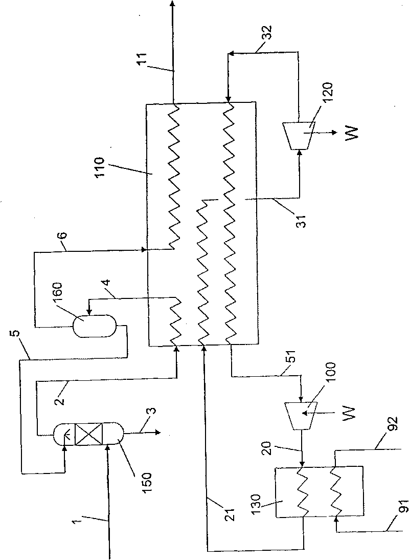
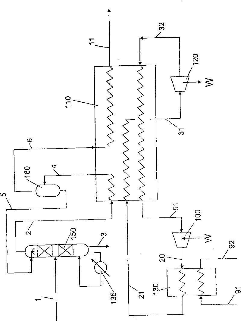
[0071] In the following example a natural gas with 90.4% methane by volume is shown to be liquefied, where the invention is used to maximize the amount of liquefied gas while minimizing Unstable hydrocarbon liquid by-product. Logistics data reference figure 1 , 2 , 3, 4 or 5.

[0072] tracking number


PUM


Abstract

A method is described for production of LNG from an incoming feed gas (1 ) on an onshore or offshore installation, and it is characterised by the following steps: 1 ) the feed gas is led through a fractionation column (150) where it is cooled and separated in an overhead fraction with a reduced content of pentane (C5) and heavier components, and a bottom fraction enriched with heavier hydrocarbons, 2) the overhead fraction from the fractionation column is fed to a heat exchanger system (110) and is subjected to a partial condensation to form a two-phase fluid, and the two-phase fluid is separated in a suitable separator (160) into a liquid (5) rich in LPG and pentane (C3-C5) which is re-circulated as cold reflux to the fractionation column (150), while the gas (6) containing lower amounts of C5 hydrocarbons and hydrocarbons heavier than C5 is exported for further processing in the heat exchanger system (110) for liquefaction to LNG with a maximum content of ethane and LPG 3) the cooling circuit for liquefaction of gas in the heat exchanger system comprises an open or closed gas expansion process with at least one gas expansion step. A system for carrying out the method is also described.

Description

technical field [0001] As can be seen from the preamble of independent claim 1, the present invention relates to a method for optimally producing LNG on a fixed or floating offshore installation. [0002] The invention also relates to a system for carrying out the process, comprising a fractionation column for feeding feed gas, a heat exchanger system for cooling and partially condensing the overhead gas stream of the fractionation column, for separating separator for the two-phase stream of the separator system, means for returning the liquid from the separator to the fractionation column and feeding this liquid as reflux to the upper part of the column, and for returning the gas from the separator to the heat exchanger system A device for further cooling and liquefaction into LNG. Contents of the invention [0003] The present invention contemplates the use of a closed gas expansion process to liquefy natural gas, and wherein the gas is first fed through a fractionation c...

Claims


Application Information

Patent Timeline
IPC IPC(8): F25J3/02F25J1/02
CPCF25J1/0092F25J2270/16F25J1/0097F25J1/0216F25J1/0037F25J1/0241F25J2210/06F25J1/0204F25J1/0087F25J2220/64F25J1/0278F25J1/0221F25J1/0057F25J1/0082F25J1/0202F25J1/005F25J2270/90F25J1/0205F25J2210/60F25J1/0052F25J1/0281F25J1/0215F25J1/0212F25J1/0232F25J1/0294F25J1/0201F25J1/0022F25J1/0072F25J1/0288F25J1/0238B01D3/14C10L3/08F25J1/02F25J3/02
Inventor 英格·斯威尔·伦德尼尔森
Owner 阿拉贡股份有限公司
Why Eureka
Try Eureka