Radio remote unit of electrically adjustable antenna and electrically adjustable antenna integrating radio remote unit
A technology of radio frequency remote equipment and ESC antenna, applied in electrical components, optical fiber radio, radio relay system, etc., can solve the problems of high cost of control devices, reduced receiving sensitivity, large signal loss, etc., and meet the requirements of reducing power capacity , The effect of improving the receiving sensitivity and reducing the hardware cost
- Summary
- Abstract
- Description
- Claims
- Application Information
AI Technical Summary
Problems solved by technology
Method used
Image
Examples
Embodiment 1
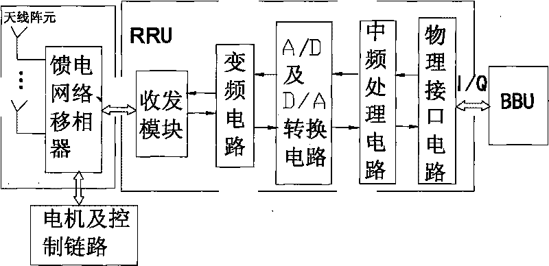
[0030] Example 1: Such as image 3 , Figure 4 , Figure 5 As shown, the remote radio equipment RRU of the electronically adjustable antenna of the present invention includes a physical interface circuit, an intermediate frequency processing circuit, an A / D and D / A conversion circuit, a frequency conversion circuit, a synthesis / distribution network, a controllable phase shifter, and a transceiver module, The downlink signal passes through the physical interface circuit, the intermediate frequency processing circuit, the A / D and D / A conversion circuit, the frequency conversion circuit, the synthesis / distribution network, the controllable phase shifter and the transceiver module in turn, and the uplink signal sequentially passes through the transceiver module and controllable phase shift Converter, synthesis / distribution network, frequency conversion circuit, A / D and D / A conversion circuit, intermediate frequency processing circuit and physical interface circuit. The physical inte...
Embodiment 2
[0036] Example 2: Such as Image 6 As shown, compared with Embodiment 1, the position of the controllable phase shifter and the transceiver module in Embodiment 2 are reversed. At this time, the transceiver channel can share a phase shifter, which not only saves the hardware cost, but also does not require uplink and downlink RF channels. Control the synchronization control of the phase shifter. However, compared with Example 1, it also has the following shortcomings:
[0037] 1. For the uplink, since the controllable phase shifter is located before the low-noise amplifier, compared to the first embodiment, the uplink receiving sensitivity will be slightly reduced;
[0038] 2. For the downlink, since the controllable phase shifter is located behind the power amplifier, the power capacity requirement of the controllable phase shifter is increased, which brings certain restrictions to the selection of the controllable phase shifter.
[0039] The design of the rest of the embodiment 2...
PUM
 Abstract
Description
Claims
Application Information
 - R&D
- Intellectual Property
- Life Sciences
- Materials
- Tech Scout
- Unparalleled Data Quality
- Higher Quality Content
- 60% Fewer Hallucinations
Browse by: Latest US Patents, China's latest patents, Technical Efficacy Thesaurus, Application Domain, Technology Topic, Popular Technical Reports.
© 2025 PatSnap. All rights reserved.Legal|Privacy policy|Modern Slavery Act Transparency Statement|Sitemap|About US| Contact US: help@patsnap.com


