
Preparation method of iron-carbon micro-electrolytic filler

A technology of iron-carbon micro-electrolysis and iron filings, applied in chemical instruments and methods, water pollutants, water/sewage treatment, etc. Weakness and other problems, to achieve the effect of promoting the reaction efficiency of the primary battery, enhancing the structural strength, and being easy to industrialize production

Inactive Publication Date: 2010-05-12
TONGJI UNIV
View PDF0 Cites 60 Cited by
  • Summary
  • Abstract
  • Description
  • Claims
  • Application Information

AI Technical Summary

Problems solved by technology

The main problem of the micro-electrolysis process using iron filings as filler is that the amount of impurities in iron filings is limited (the impurities in cast iron are less than 5%), the micro-electrolysis is relatively weak, and the reduction reaction is mainly used, so the application is restricted
Using copper as the cathode can increase the reduction reaction rate, but the cost of iron-copper composite filler is high

Method used


Image

  • Preparation method of iron-carbon micro-electrolytic filler
  • Preparation method of iron-carbon micro-electrolytic filler
  • Preparation method of iron-carbon micro-electrolytic filler

Examples


Embodiment 1

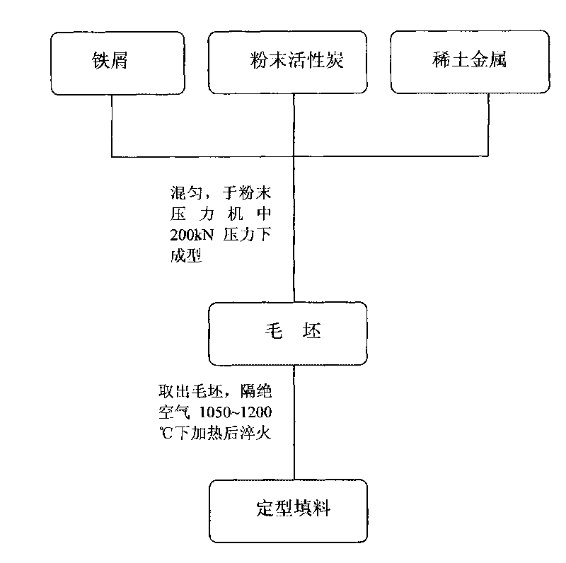
[0020] First use 5% hydrochloric acid to pickle the iron filings with a particle size of less than 60 mesh for 20 minutes, and rinse them with water; then put the iron filings, powdered activated carbon and rare earth metals with a particle size of -B-2) After mixing evenly according to the following mass percentage, add it to a model in the shape of a Pall ring. The diameter of the Pall ring is 50 mm, the height is 30 mm, and it is coated with release oil. In the mixture, iron filings account for 85%, powdered activated carbon accounts for 14.91-14.99%, and rare earth metal accounts for 0.01-0.09%. The mixture is pressed and formed by a powder press under a pressure of 200kN, and the blank is taken out to obtain a blank. After the blank is taken out, it is isolated from the air and heated at 1050-1200°C for 90-100 minutes, then quenched, and finally the shaped iron-carbon micro-electrolytic filler is obtained.

[0021] The effect of the iron-carbon micro-electrolytic filler p...

Embodiment 2

[0024] The iron-carbon micro-electrolytic filler prepared in Example 1 was used to treat coking wastewater. The water used in the experiment was taken from a coking plant to adjust the water quality of the pool: COD was 3780mg / L, volatile phenol was 524mg / L, and the chroma was 400. First adjust the pH to 3, after micro-electrolysis treatment, the reaction time is 90min, micro-aeration, after the reaction, adjust the pH with sodium hydroxide, measure its COD, phenol value and chroma, see the treatment effect image 3 Shown: after the reaction, the effluent COD is 2170mg / L, and the removal rate is 42.6%; the volatile phenol is 295mg / L, and the removal rate is 43.7%; the chroma is 50, and the removal rate is 87.5%. During the continuous experiment, the shape of the filler remained good, and no cracking and hardening occurred.


PUM

PropertyMeasurementUnit
particle size (mesh)aaaaaaaaaa
clearance rateaaaaaaaaaa

Abstract

A preparation method of iron-carbon micro-electrolytic filler relates to a preparation method of the micro-electrolytic filler for treating wastewater, comprising the following steps: using scrap iron with grain diameter of less than 60 meshes, active carbon powder with grain diameter of less than 100 meshes and rare-earth metal powder as raw materials; using hydrochloric acid solution with mass percentage of 5% for acid washing the scrap iron to activate the scrap iron; mixing the scrap iron with the active carbon powder and the rare-earth metal powder on mass percent of 85%: (14.91-14.00)%: (0.01-0.09)%; using a press machine to add the powder mixture to a Bauer ring-shaped mould for molding at 200 kN; demolding to obtain rough product; heating the rough product for 90-100 min at 1050-1200 DEG C in the absence of air; and then annealing to obtain the iron-carbon micro-electrolytic filler. The iron-carbon micro-electrolytic filler has good specific surface, excellent micro-electrolytic effect and simple technique, and is capable of effectively preventing passivation of the filler surface and hardening of the filler; moreover, the preparation method is easy to promote and suitable for industrial production.

Description

technical field [0001] The invention discloses a method for preparing an iron-carbon micro-electrolytic filler, relating to a method for preparing a micro-electrolytic filler for wastewater treatment. Specifically, the method for preparing micro-electrolytic fillers is based on iron filings and powdered activated carbon as main raw materials. Background technique [0002] Since the micro-electrolysis technology was introduced into my country in the 1980s, it has been widely used in the treatment of wastewater from dyes, petrochemicals, heavy metals, pharmaceuticals, and pesticides. The technology has also developed from a single micro-electrolysis technology to a combined wastewater treatment organically combined with other technologies. technology. The iron-carbon micro-electrolysis method can pretreat biological refractory wastewater, so as to realize the opening and chain breaking of macromolecular organic pollutants, improve the biodegradability of wastewater, and facili...

Claims


Application Information

Patent Timeline
Patent Type & Authority Applications(China)
IPC IPC(8): C02F1/463C02F101/30
Inventor 潘碌亭王键吴锦峰余波王文蕾
Owner TONGJI UNIV
Learn More