High grain wide frequency band omni-directional antenna

An omnidirectional antenna and broadband technology, which is applied to antennas, electrical components, etc., can solve the problems that dual-band broadband high-gain antennas cannot meet requirements, antennas cannot meet communication needs, and frequency band control is difficult. , increase the length, design the effect of flexible

Inactive Publication Date: 2010-04-28
JIANGSU ANTENAI TECH
View PDF0 Cites 3 Cited by
  • Summary
  • Abstract
  • Description
  • Claims
  • Application Information

AI Technical Summary

Problems solved by technology

At the same time, solve some shortcomings of the existing antenna: (1) At present, the gain of the antenna is required to be relatively high, for example, a gain of 5-6dBi is required, and most of the existing antennas are dipole antennas and monopole antennas, and the directional diagrams are equal up and down , so a part of the electric wave is consumed, so the gain is relatively low
The current antennas cannot meet the current communication needs, especially the dual-band broadband high-gain antennas cannot meet the requirements
(4) Most of the current cell coverage and beautification antennas use monopole antennas and dipole antennas, and it is difficult to control the frequency band. At the same time, in order to make full use of existing resources and adapt to the needs of different environments, the antenna design is required to be flexible. Can meet the needs of different occasions
Moreover, the products developed are all directional antenna products. Although there are a few broadband omnidirectional antenna products, they are complex in structure, cumbersome in design, poor in versatility, high in processing cost, and have certain defects in performance, so they are not suitable for promotion. Cell coverage has caused certain difficulties, so the development of multi-band, miniaturized, simple structure, flexible design, and low-cost broadband omnidirectional antenna is the top priority of today's research

Method used


Image

  • High grain wide frequency band omni-directional antenna
  • High grain wide frequency band omni-directional antenna
  • High grain wide frequency band omni-directional antenna

Examples


Embodiment Construction

[0013] The present invention will be described in further detail below in conjunction with the accompanying drawings and specific embodiments.

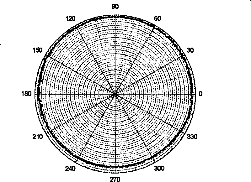
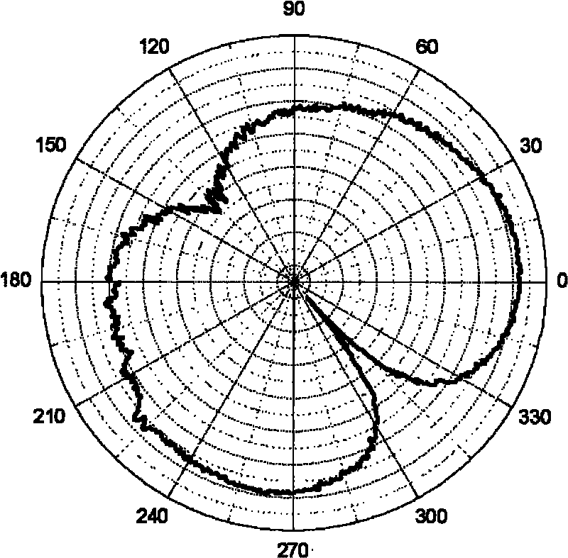
[0014] Such as Figure 1 to Figure 3 , where 1 is the vertical patch unit, 2 is the loaded circular patch, 3 is the ground wire, 4 is the outer conductor of the dummy joint, 5 is the ground plate, 6 is the fixed base, 7 is the fixing device, 8 is the main feeder, 9 is polytetrafluoroethylene, 10 is a dummy joint, 11 is an orthogonal radiation unit, and 12 is an inner conductor of a dummy joint.

[0015] A high-gain broadband omnidirectional antenna includes a ground plate, a main radiation unit, a loaded radiation unit and a feed structure.

[0016] The main radiating unit of the antenna adopts vertical patches to form an orthogonal structure (that is, the vertical patch unit 1 is perpendicular to the orthogonal radiating unit 11); there is a loading radiating unit (ie, loading circular patch 2) on it.

[0017] The main feeder 8 and...


PUM


Abstract

The invention provides a high grain wide frequency band omni-directional antenna, comprising two orthogonal radiation units, a load radiation unit, a direct current path, a grounding plate and a feeding structure. The radiation unit of the antenna partially uses vertical patches to constitute an orthogonal structure, and the load radiation unit thereon effectively advances the radiation direction diagram on the azimuth plane, the direct current short circuit probe and load feeding technique, thereby not only expanding the bandwidth of the antenna but also reducing the size of the antenna. The invention has higher radiation efficiency and higher grain, thereby advancing the communication quality and improving the communication environment, adding the work bandwidth of the antenna, improving the impedance bandwidth of the antenna, having low cost and being convenient for mass production.

Description

technical field [0001] The invention relates to a broadband omnidirectional antenna for transmitting and receiving radio signals in all communication networks in the field of communication and mobile communication. Background technique [0002] As radio communication equipment and electronic information equipment are developing toward multi-functionality, miniaturization, ultra-wideband and friendly coordination with the surrounding environment, this makes broadband and miniaturization one of the hot research topics at home and abroad. It involves the broadband impedance matching technology of the antenna, the loading technology of the antenna, the vertical patch technology, the reactance compensation technology of the antenna, the optimized design of the small antenna shape and other advanced technologies and processes. At the same time, solve some shortcomings of existing antennas: (1) At present, the gain of the antenna is required to be relatively high, for example, a ga...

Claims


Application Information

Patent Timeline
Patent Type & Authority Applications(China)
IPC IPC(8): H01Q13/08
Inventor 邢红兵徐燕李迎松刘乘源姜兴文吴成云王积祥李渠塘
Owner JIANGSU ANTENAI TECH
Why Eureka
Try Eureka