
Water lubrication dynamic and static pressure ladder groove step bearing

A stepped bearing, dynamic and static pressure technology, applied in the direction of bearings, bearing components, shafts and bearings, etc., can solve the problems of reducing bearing reliability, instability of the spindle center position, cavitation of lubricating medium, etc.

Inactive Publication Date: 2010-04-21
XI AN JIAOTONG UNIV
View PDF0 Cites 2 Cited by
  • Summary
  • Abstract
  • Description
  • Claims
  • Application Information

AI Technical Summary

Problems solved by technology

[0004] (1) Low-viscosity lubricating medium is generally used under high-speed working conditions. Due to the low viscosity of the medium, severe turbulent flow will occur when the spindle speed is high, the internal friction of the lubricating medium will increase, and the temperature rise of the bearing will increase.
[0005] (2) Under high-speed working conditions, the lubricating film of the sliding bearing is prone to rupture, causing cavitation inside the lubricating medium and reducing the reliability of the bearing
[0006] (3) Under high-speed working conditions, the stability of the oil film of the sliding bearing is reduced, the working state of the bearing is unstable, and it is easy to enter the state of oil film oscillation, resulting in the instability of the spindle axis position and even accidents

Method used


Image

  • Water lubrication dynamic and static pressure ladder groove step bearing
  • Water lubrication dynamic and static pressure ladder groove step bearing
  • Water lubrication dynamic and static pressure ladder groove step bearing

Examples


Embodiment Construction

[0015] The present invention will be described in further detail below in conjunction with the accompanying drawings.

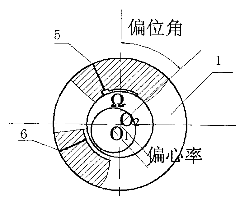
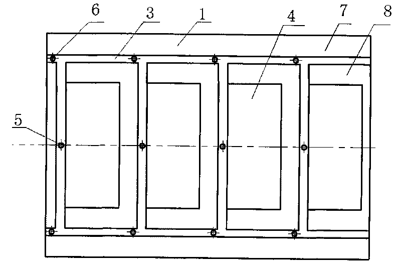
[0016] Referring to Fig. 1, including the bearing bush 1 and the main shaft 2 arranged in the bearing bush 1, a trapezoidal ring groove 3 is opened on the inner wall of the bearing bush 1, that is, the oil seal surface of the bearing, and the trapezoidal ring groove 3 divides the bearing bush into several In the annular groove 3 of the trapezoidal structure, there is a shallow cavity 4 with a depth smaller than that of the annular groove 3, and on the bearing bush 1, there are oil inlet holes 5 and cooling holes connected to the annular groove 3 of the trapezoidal structure. Hole 6.

[0017] This invention has following three advantages:

[0018] 1. Reduce the temperature rise of the bearing outlet

[0019] The ring groove 3 of the trapezoidal structure divides the axial oil sealing surface 7 with strong dynamic pressure effect into two parts, forming a hyd...


PUM


Abstract

The invention relates to a water lubrication dynamic and static pressure ladder groove step bearing, comprising a bearing pad and a main shaft arranged in the bearing pad. The inner wall of the bearing pad which is also the oil sealing surface of a bearing is provided with an annular ladder-shaped groove; the bearing pad is separated into a plurality of mutually communicated areas by the annular ladder-shaped groove; the annular ladder-shaped groove is internally provided with shallow cavities; and the bearing pad is also provided with oil inlet holes and cooling holes which are both communicated with the annular ladder-shaped groove. In the invention, the oil sealing surface of the bearing is provided with the ladder-shaped deep groove for dividing the surface of the bearing into a plurality of areas, and the shallow cavities with depth less than that of the groove are arranged in the areas surrounded by the ladder-shaped groove. The shallow cavities surrounded by the ladder-shaped groove can enhance the dynamic pressure and improve the bearing capability and rigidity of the bearing. A plurality of oil supply holes and cooling holes are arranged in the ladder-shaped groove so that high-pressure lubricating medium can be pumped into the gaps of the bearing through the small holes, the flow rate of the surface of the bearing pad is improved, the temperature raising is reduced, and the continuity of the oil film is ensured.

Description

technical field [0001] The invention relates to a high-speed main shaft support bearing, in particular to a water-lubricated dynamic and static pressure stepped groove stepped bearing capable of improving high speed, stability and low temperature rise for a high-speed main shaft. Background technique [0002] Existing high-speed sliding bearings mainly include the following categories: 1. Spiral groove oil chamber (M Tomio, NTakashi, I Fumihiro. Development and performance test for high-speed spindle with water lubricated hybrid journal bearing[J].Nihon kikai gakkai nenji taikai koen ronbunshu, 2001, 3(1): 211-212. Yoshimoto, S.Kume. Axial load capacity of water-lubricatedhydrostatic conical bearings with spiral grooves for high speedspindles[J]. Tribology international, 1998, 31(6): 331- 338.), mainly used in the case of both radial and axial loads; 2. Cavityless hydrostatic bearings (SC Sharma, V Kumar, SC Jain, et al. Thermohydrostatic analysis of slot-entry hybrid journa...

Claims


Application Information

Patent Timeline
IPC IPC(8): F16C32/06F16C33/10F16C37/00
Inventor 徐华戴攀马石磊
Owner XI AN JIAOTONG UNIV
Learn More