
System and method for on-site point-by-point calibration of brightness and chrominance of the whole screen of LED display screen

A technology of LED display and calibration system, applied in static indicators, instruments, etc., can solve the problems of uneven color, difficult implementation, low adjustment efficiency, etc., to achieve uniform pixels, reduce processing costs, and ensure the effect of correction effect

Inactive Publication Date: 2010-04-07
HUIZHOU DESAY INTELLIGENT TECH
View PDF2 Cites 81 Cited by
  • Summary
  • Abstract
  • Description
  • Claims
  • Application Information

AI Technical Summary

Problems solved by technology

[0003] However, due to the inherent brightness and color wavelength dispersion of the LED light-emitting diode, the basic light-emitting element of the LED display, it is difficult to achieve the exact sameness accepted by the human eye even through screening. Uniform and uneven color mottling
Some high-end manufacturers use strict uniform calibration of brightness and chromaticity for each single module that makes up the screen before leaving the factory, which can greatly eliminate the mottled phenomenon, but the calibration equipment is expensive, the calibration environment is harsh, and the calibration efficiency is low. and other shortcomings
[0004] There is another major disadvantage in the existing adjustment method for LED display screens: After leaving the factory, with the passage of time, many LEDs and modules on the display screen have different attenuation characteristics, mottled and bright and dark blocks. The phenomenon will gradually intensify
However, when collecting data in each area, since the acquisition angle and position of the acquisition equipment will be different, this will inevitably cause a jump in the correction data from the edge of one area to the edge of another area, and finally the display screen will display the data in units of the acquisition area. Obvious horizontal and vertical stripes
In addition, when the pixel pitch of the LED display screen to be tested is small and the pixel points are dense, the interference between adjacent points will make this method difficult to implement

Method used


Image

  • System and method for on-site point-by-point calibration of brightness and chrominance of the whole screen of LED display screen
  • System and method for on-site point-by-point calibration of brightness and chrominance of the whole screen of LED display screen
  • System and method for on-site point-by-point calibration of brightness and chrominance of the whole screen of LED display screen

Examples


Embodiment Construction

[0034] In order to facilitate the understanding of those skilled in the art, the principles of the system and method of the present invention will be further described in detail below in conjunction with specific embodiments and accompanying drawings:

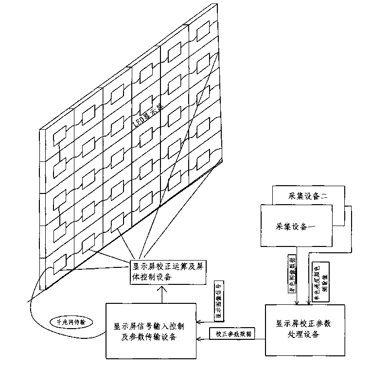
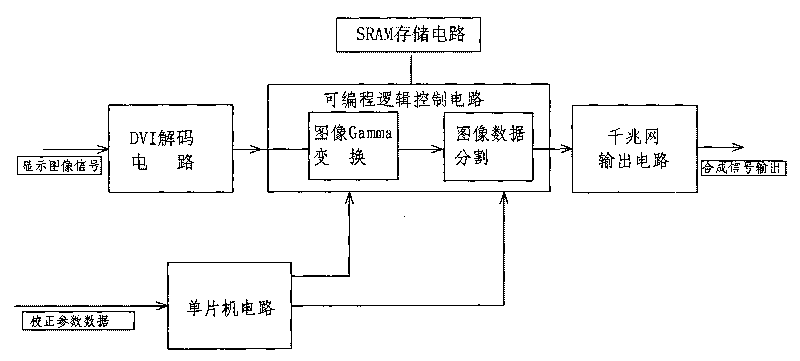
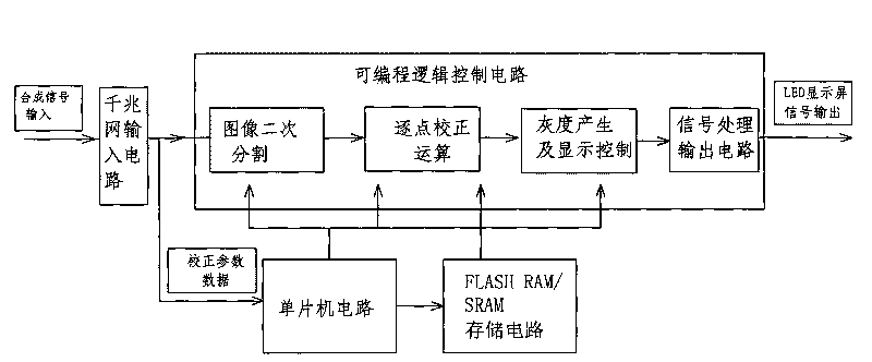
[0035] as attached figure 1As shown, the system of the present invention includes LED display optical parameter acquisition equipment, display calibration parameter processing equipment, display signal input control and parameter transmission equipment, and display calibration calculation and screen body control equipment.

[0036] Wherein, described on-the-spot LED display screen optical parameter acquisition equipment is divided into two parts: acquisition equipment one selects to be used for acquiring the single-lens reflex digital camera of display screen display red, green, blue monochrome, original LED luminance chromaticity relative difference image information; Acquisition Device 2 selects the bright color measuring ins...


PUM


Abstract

The invention discloses a system and a method for on-site point-by-point calibration of the brightness and chrominance of the whole screen of an LED display screen. The system comprises LED display screen optical parameter acquisition equipment, display screen calibration parameter processing equipment, display screen signal input control and parameter transmission equipment and display screen calibration operation and screen control equipment. The method comprises the following steps: acquiring image data of information on original red, green and blue values of a single point in the lightened part of the LED display screen and values of actual brightness and colors when single colors of red, green, blue and while are displayed; and determining the calibration coefficients of the single point to realize calibration. The method acquires data by in a way of uniformly distributing the luminous points of the display screen in arrays which have the same point number and shape and alternately distributed at equal intervals, thereby avoiding clear horizontal and vertical patterns which use an acquisition area as a unit and are caused by the jump of regional edge calibration data when an original suborigin acquires data and interference among adjacent points caused by reduced pixel pitch and ensuring the calibration effect.

Description

technical field [0001] The invention relates to the field of image display correction, in particular to a system and a corresponding correction method for on-site point-by-point brightness and chromaticity correction of the entire LED display screen. Background technique [0002] The LED display achieves the effect of reproducing many colors in nature by adjusting the different light-emitting ratios of red, green and blue LED light-emitting diodes in a single pixel. Compared with LCD, plasma screen, projection and other display devices, it has the advantages of good color reproduction, high brightness, long life, short response time, energy saving and environmental protection, and size can be adjusted arbitrarily. It has been widely used in airports, stations, docks, shopping malls, Landmark buildings, conferences, exhibitions, performances, municipal squares, stadiums and many other public places. [0003] However, due to the inherent brightness and color wavelength disper...

Claims


Application Information

Patent Timeline
IPC IPC(8): G09G3/32
Inventor 王勇巫辉祥何平刘春明李朝阳
Owner HUIZHOU DESAY INTELLIGENT TECH
Learn More