
System and method for recovering high-speed 8PSK clocks parallelly

A clock recovery, high-speed technology, applied in transmission systems, digital transmission systems, electrical components, etc., can solve problems such as large error jitter, no specific range of correction coefficients, and insufficient utilization

Active Publication Date: 2010-03-17
XIAN INSTITUE OF SPACE RADIO TECH
View PDF0 Cites 7 Cited by
  • Summary
  • Abstract
  • Description
  • Claims
  • Application Information

AI Technical Summary

Problems solved by technology

[0009] "An Improved QAM Signal Clock Error Detection Algorithm" (Volume 32, Issue 7, TV Technology, 2008), aimed at the characteristics of large clock loop error jitter of multi-level signals, proposed an improved error calculation formula, but did not give The specific range of the correction coefficient is calculated, and only three sampling points are used in the calculation, and the information carried by other sampling points is not fully utilized. The calculated error will inevitably cause delays in the clock loop locking and deviation from the locking point.

Method used


Image

  • System and method for recovering high-speed 8PSK clocks parallelly
  • System and method for recovering high-speed 8PSK clocks parallelly
  • System and method for recovering high-speed 8PSK clocks parallelly

Examples


Embodiment Construction

[0051] For the demodulation of high-speed 8PSK signals, limited by the internal processing clock of the device, a parallel clock recovery method is required. Under the condition that the highest frequency of the system remains unchanged, if the single channel data is processed in N channels in parallel, the demodulation code rate can be increased by N times. Of course, the resources required by the parallel structure compared with the single channel are also increased by N times accordingly. So this is actually a strategy of exchanging resources for speed.

[0052] The parallel clock recovery system and method of the present invention are introduced below through the system block diagram of the high-speed parallel digital receiver. The structural block diagram of the parallel clock loop applied by the parallel high-speed digital receiver is as follows figure 1 As shown, the 8PSK modulated signal of the radio frequency is demodulated and received by the method of coherent demod...


PUM


Abstract

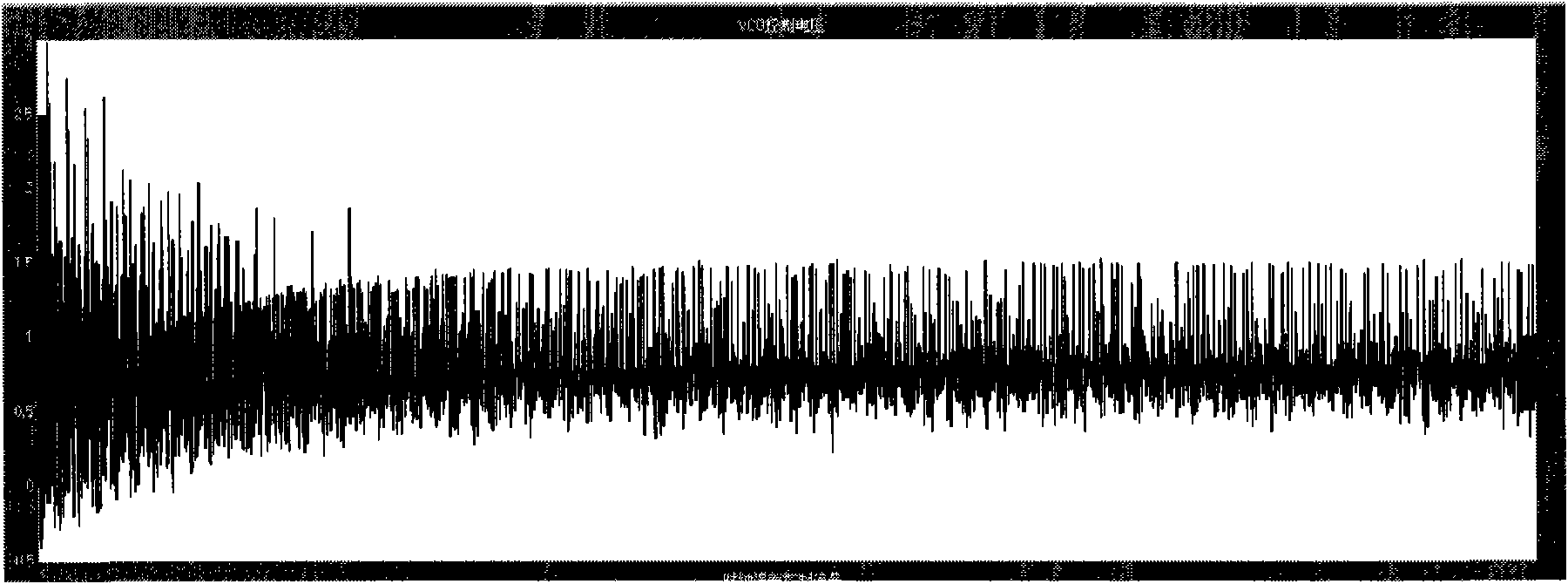
The invention provides a system and a method for recovering high-speed 8PSK clocks parallelly, which is characterized in that a parallel clock error extraction module, a clock scanning module, a clocklocking indication extraction module and a voltage-controlled crystal oscillator (VCXO) form a clock loop. The parallel clock error extraction module carries out S-fold sampling rate sampling on thebaseband data output by a high-speed parallel digital receiver, generates a clock error signal epsilonT and sends the epsilonT to the VCXO and the clock scanning module. The clock scanning module carries out clipping on the received clock error signal epsilonT, accumulates the clipped clock error signals and takes the mean, thus obtaining the scanning curve of the clock loop. The clock locking indication extraction module determines the threshold of clock locking indication according to the scanning curve generated by the clock scanning module and sends the threshold to the VCXO. The VCXO continuously adjusts the output frequency according to the received clock error signal epsilonT, when the clock locking indication reaches the threshold, the output frequency is stabilized and the sampling clock samples the maximum point, thus realizing clock recovery.

Description

technical field [0001] The invention relates to the field of digital communication, specifically belongs to the field of high-speed digital demodulators, and refers to a method for demodulating 8PSK signals and realizing clock synchronization in parallel. Background technique [0002] With the increasing communication capacity, the radio frequency spectrum of the remote sensing satellite system becomes more and more crowded, the data rate continues to increase, and the required bandwidth becomes wider and wider, which makes the mutual interference between channels quite prominent. In this case, the TCM 8PSK modulation technology is a solution developed in recent years to solve the effectiveness and reliability of the communication system. It can obtain significant coding gain without increasing the signal bandwidth or reducing the effective information transmission rate. Suitable for information transmission in bandwidth-constrained channels. [0003] The rapid development...

Claims


Application Information

Patent Timeline
Patent Type & Authority Applications(China)
IPC IPC(8): H04L7/00
Inventor 谢耀菊杨新权杨光文李立平一帆
Owner XIAN INSTITUE OF SPACE RADIO TECH
Learn More