
Solar heating heat-accumulating system

A heat storage system and solar collector technology, applied in the field of solar heating and heat storage systems, can solve the problems of large indoor temperature fluctuation, complex device structure, large water temperature fluctuation, etc., to improve heating comfort, small size, storage Thermal power effect

Active Publication Date: 2011-11-16
CHINA ELECTRONICS TECH GRP CORP NO 14 RES INST
View PDF2 Cites 0 Cited by
  • Summary
  • Abstract
  • Description
  • Claims
  • Application Information

AI Technical Summary

Problems solved by technology

The completed demonstration projects generally use hot water tanks to store heat, which are bulky, and the water temperature fluctuates greatly. The solar radiation increases the water temperature, and the solar radiation decreases the water temperature, resulting in large indoor temperature fluctuations during the heating process.
[0004] Chinese patent CN2731356Y relates to a flat-plate solar phase change heat storage heating device, which uses phase change materials to store heat. The device integrates lighting, heat storage, heat exchange, and heat preservation. Secondary heat exchange is required in the process of heat storage and heating. , that is, the collector exchanges heat with the heat transfer medium during heat storage, the heat transfer medium exchanges heat with the rod-shaped black body heat storage element, the heat storage element exchanges heat with the heat transfer medium during heating, and the heat transfer medium exchanges heat with the water in the coil, resulting in the entire device Complex structure, low thermal efficiency
This mode of operation has the problems of complex system, large fluctuations in water temperature, large fluctuations in room temperature, complex control, and low reliability, and is not suitable for general household use.

Method used


Image

  • Solar heating heat-accumulating system
  • Solar heating heat-accumulating system

Examples


Embodiment Construction

[0020] The present invention will be described in further detail below in conjunction with the accompanying drawings and specific embodiments.

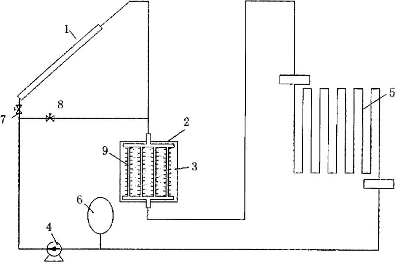
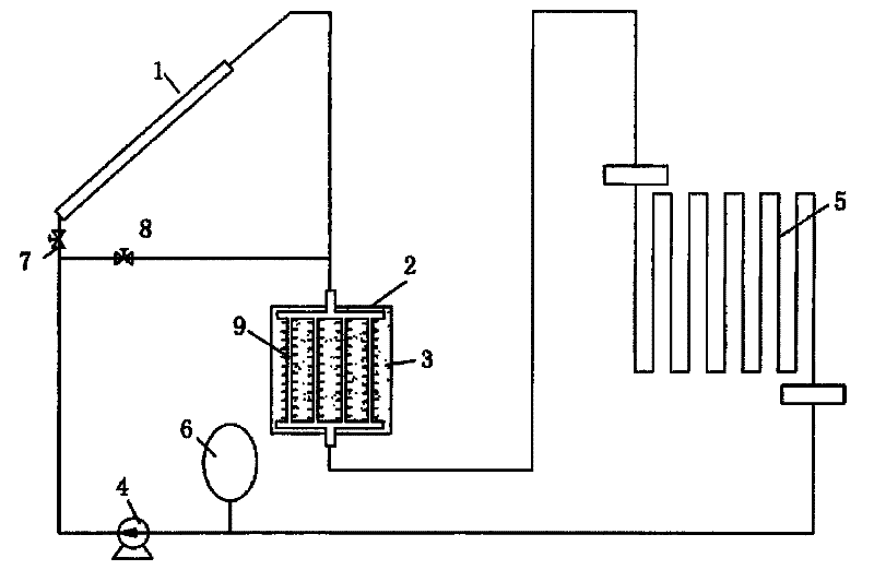
[0021] Such as figure 1 As shown, 1 is the solar collector, 2 is the heat accumulator, 3 is the heat storage material, 4 is the circulation pump, 5 is the heating terminal, 6 is the expansion tank, 7 is the valve at the inlet of the collector, and 8 is the bypass Valve, 9 are finned tubes.

[0022] The solar heating heat storage system includes a solar heat collector 1 , a heat accumulator 2 , a circulating pump 4 , a heating terminal 5 , an expansion tank 6 , a valve 7 at the inlet of the heat collector, and a bypass valve 8 .

[0023] The heating system adopts a closed cycle. The outlet of the solar collector 1 is connected to the heat accumulator 2. The heat accumulator 2 is connected in series with the heating terminal 5. A circulation pump 4 is installed at the outlet of the heating terminal 5. The solar collector 1 is connected...


PUM


Abstract

The invention relates to a solar heating heat-accumulating system, comprising a solar thermal collector (1), a heat accumulator (2), a circulating pump (4), heating terminals (5), an expansion pot (6), a heat accumulator inlet valve (7) and a bypass valve (8). The system uses closed cycle; the outlet of the solar thermal collector (1) is connected with the heat accumulator (2) which is connected with the heating terminals (5) in series; the outlets of heating terminals (5) are provided with the circulating pump (4); a bypass is arranged between the solar thermal collector (1) and the heat accumulator (2) and is provided with the bypass valve (8) thereon; the expansion pot (6) is arranged on a pipeline; the structure of the heat accumulator (2) is in the mode of a heat exchanger, and hot water is not directly contacted with heat accumulating materials; the heat accumulator (2) is a square box or a cylindric pot, the box is filled with the heat accumulating materials (3), finned tubes (9) are arranged between the heat accumulating materials (3), and water can flow through the finned tubes (9) to exchange heat with the heat accumulating materials (3).

Description

technical field [0001] The invention relates to a solar heating heat storage system, which is suitable for solar heat utilization. Background technique [0002] At present, my country's energy shortage and serious environmental pollution, vigorously developing solar thermal utilization is an important way to alleviate energy shortage. Solar heating is an important branch of solar thermal utilization, but due to high cost and technology that needs to be improved, solar heating has not been developed. For large-scale applications, only a small number of demonstration projects have been built. [0003] A key technology in solar heating is heat storage. The energy flow density of solar radiation is low, and affected by cloudy days and nights, it cannot continuously heat the house. Therefore, a heat storage device is needed to store the solar energy obtained during the day. , for night or cloudy use. The completed demonstration projects generally use hot water tanks to store hea...

Claims


Application Information

Patent Timeline
Patent Type & Authority Patents(China)
IPC IPC(8): F24J2/00F24D11/00F24J2/34F24J2/46
CPCY02E10/40Y02B10/20
Inventor 钱吉裕战栋栋
Owner CHINA ELECTRONICS TECH GRP CORP NO 14 RES INST
Learn More