
Standard magnetic suspension hybrid bearing-supported rotor and high-speed induction electrical rotating machine

An electric rotating and hybrid bearing technology, applied in the direction of bearings, shafts and bearings, mechanical equipment, etc., can solve the problems of high cost, soft end ring and bar end material, complicated process, etc., and achieve the effect of stable operation.

Inactive Publication Date: 2010-03-03
何君 +2
View PDF0 Cites 10 Cited by
  • Summary
  • Abstract
  • Description
  • Claims
  • Application Information

AI Technical Summary

Problems solved by technology

It is understood that the foreign copper cage manufacturing process uses vacuum melting and welding copper powder to form copper strips, which is similar to the powder metallurgy high-temperature sintering process, which can ensure the fit between the copper strips and the iron core channel, but the process is complicated and the cost is too high And the technology is not mature
[0005] Another process is that the end ring and the guide bar of the copper cage rotor core winding are connected by welding, but this leads to the softening of the material at the end ring and the end of the guide bar after welding, which cannot resist the ultra-high-speed rotation of the material Generally, a protective sleeve should be added to the end ring, but this will cause the heat dissipation condition of the end ring to deteriorate.

Method used


Image

  • Standard magnetic suspension hybrid bearing-supported rotor and high-speed induction electrical rotating machine
  • Standard magnetic suspension hybrid bearing-supported rotor and high-speed induction electrical rotating machine
  • Standard magnetic suspension hybrid bearing-supported rotor and high-speed induction electrical rotating machine

Examples


Embodiment Construction

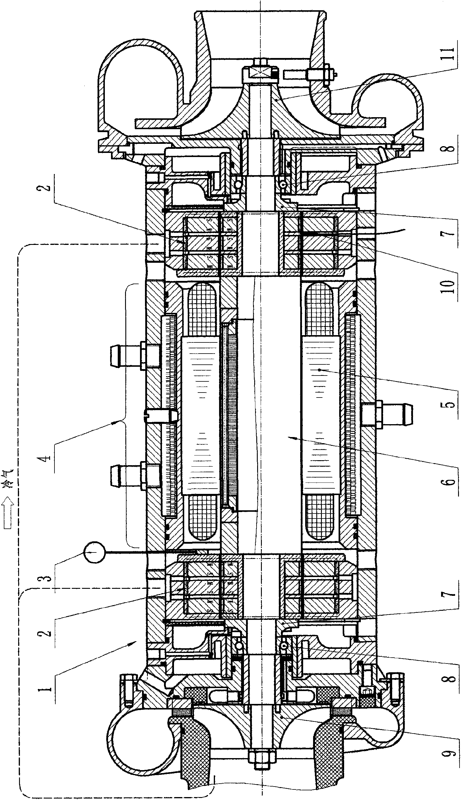
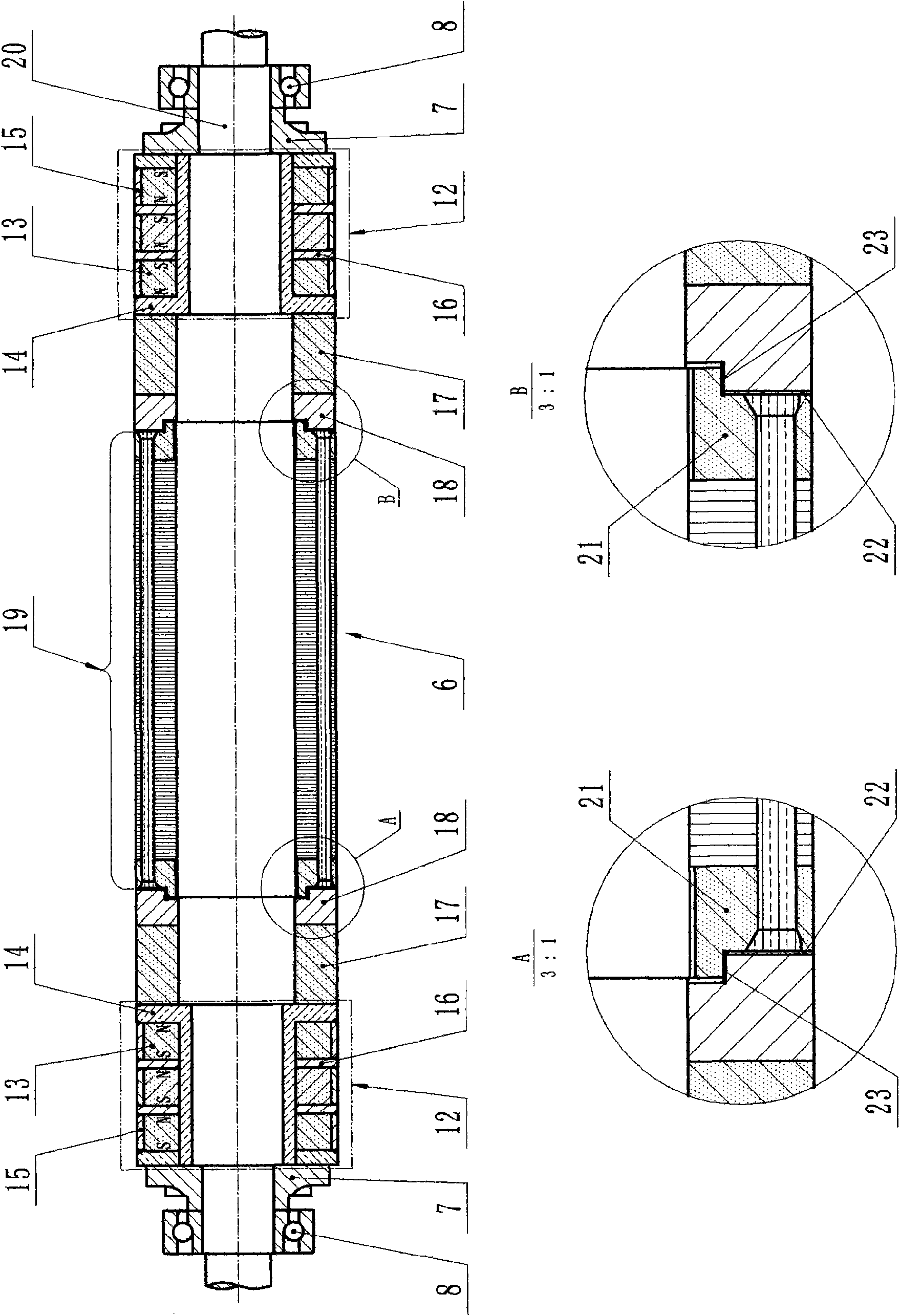
[0018] Specific embodiments of the present invention will be described below in conjunction with the accompanying drawings. figure 1 It is shown as a front view of an air refrigerator 1 directly driven by an electric motor including a quasi-maglev hybrid bearing supported rotor 6 of the present invention. figure 1 Among them, the air refrigerator 1 includes an electric motor 4 in its middle. The electric motor 4 includes a rotor 6 and a stator 5 supported by quasi-maglev hybrid bearings. The rotor 6 uses a pair of three sets of permanent magnetic radial bearings 2 as the main support, and a pair of angular contact ball bearings 8 as the radial auxiliary support, and together with a pair of sliding thrust bearings 7 bear the axial thrust. There are fan blades on the sliding thrust bearing 7 to cool the angular contact ball bearings 8. When the low-pressure lubricating oil is sprayed onto the high-speed rotating sliding thrust bearing 7, the fan blades on it will beat the lubri...


PUM


Abstract

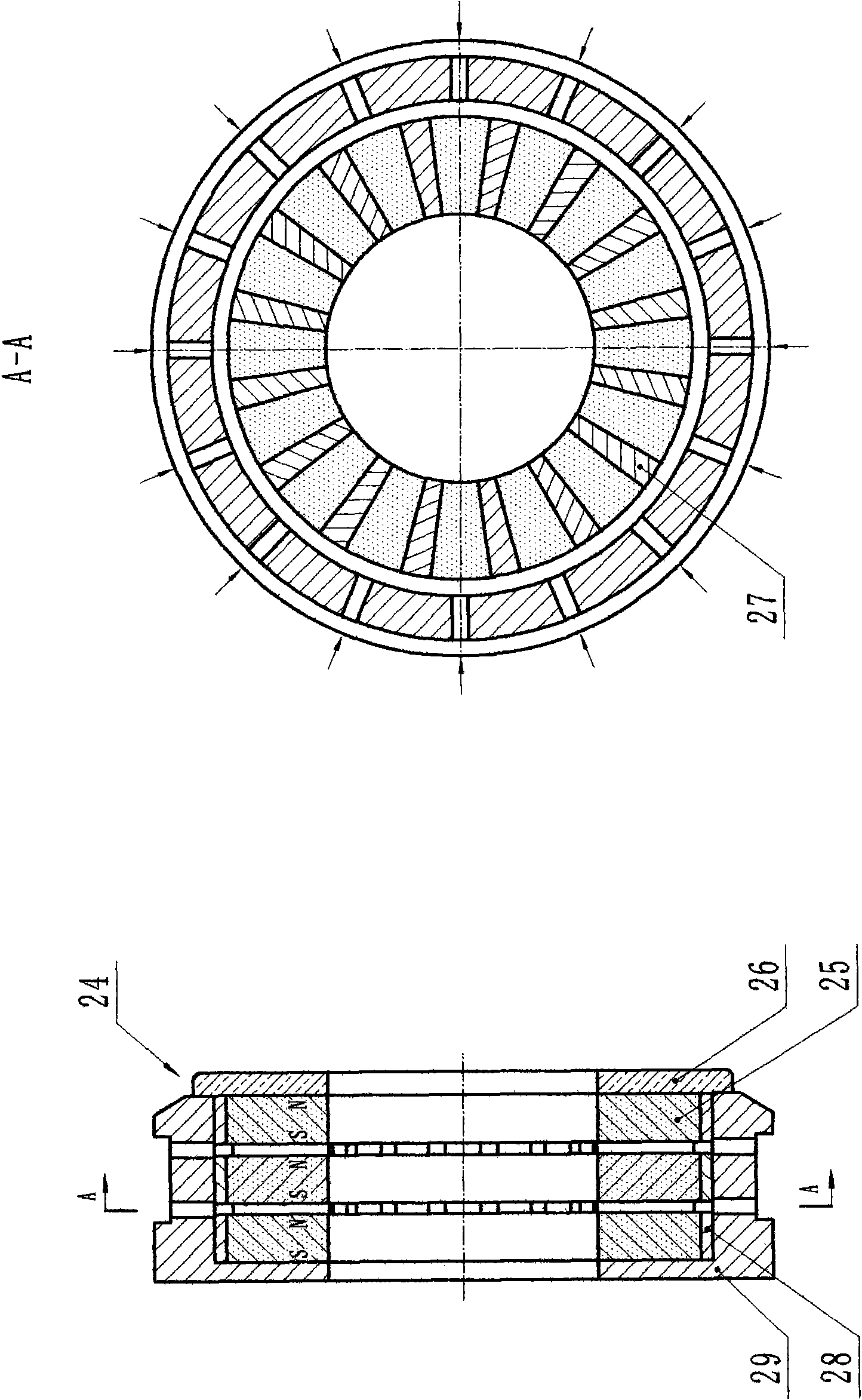
The invention discloses a standard magnetic suspension hybrid bearing-supported rotor for a high-speed induction electrical rotating machine, which comprises a standard magnetic suspension supportingsystem with permanent magnetic suspension and a rolling bearing for auxiliary support, a rotor core winding and a rotating shaft, wherein in the standard magnetic suspension supporting system, a permanent magnetic radial bearing adopts a plurality of parallel groups of axially magnetized inner and outer magnetic rings and an angular contact ball bearing is used for providing radial auxiliary support and withstands an axial push thrust with a thrust bearing; a rotor core lamination adopts a circular closed slot and a core winding adopts cold riveting joint; the inner magnetic rings are providedwith magnetic insulation inner sleeves and outer layer protective sleeves and cooling air ducts are preserved between the outer magnetic rings. The standard magnetic suspension hybrid bearing-supported rotor and the high-speed induction electrical rotating machine of the invention ensure that the peripheral velocity of the rotor is stably up to over 200m / s and the effect is remarkable.

Description

technical field [0001] The present invention relates to a quasi-magnetic suspension hybrid bearing-supported rotor for high-speed induction electric rotating machines, in particular to rotors for large-capacity air refrigerators, air compressors, etc. driven by high-speed induction motors, wherein the rotor is for example not High-speed rotation of less than tens of thousands of revolutions per minute. The invention also relates to other high speed induction electric rotating machines including the rotor. Background technique [0002] There are two main technical problems to be solved in the design of high-power, high-speed high-speed induction motors (20kw, above 60000 / min): one is the bearing design; the other is to prevent the rotor from being deformed and damaged when the motor rotates at high speed. At present, the bearing design of this kind of high-power, high-speed motor generally considers the active magnetic bearing support method of hybrid support of electromagne...

Claims


Application Information

Patent Timeline
IPC IPC(8): H02K7/08H02K7/09H02N15/00F16C32/04
Inventor 何君伍怀秋何应明
Owner 何君
Learn More