
Low-noise micro-arc oxidation device

A micro-arc oxidation, low-noise technology, applied in the direction of anodic oxidation, can solve the problem of high noise, achieve the effect of safe reduction, reduction of transmission intensity, and easy observation and detection

Active Publication Date: 2011-01-19
HARBIN INST OF TECH
View PDF0 Cites 2 Cited by
  • Summary
  • Abstract
  • Description
  • Claims
  • Application Information

AI Technical Summary

Problems solved by technology

[0004] The purpose of the present invention is to provide a low-noise micro-arc oxidation device to solve the problem of high noise in the micro-arc oxidation process of the existing micro-arc oxidation device

Method used


Image

  • Low-noise micro-arc oxidation device
  • Low-noise micro-arc oxidation device
  • Low-noise micro-arc oxidation device

Examples


specific Embodiment approach 1

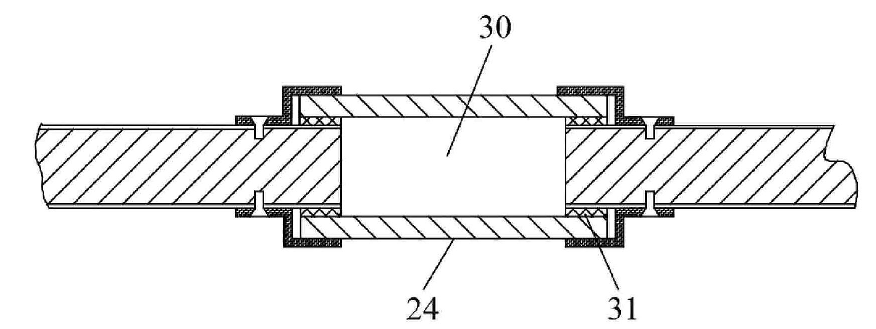
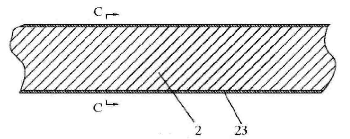
[0008] Specific implementation mode one: combine Figure 1-Figure 6 Describe this embodiment, the micro-arc oxidation device of this embodiment includes a box body 1, a gas discharge pipe 4, an exhaust fan 5, an air pump 6, an air pipe 7, a cooling water pump 11, a cooling water inlet pipe 12, and a barrel-shaped cooling water jacket. Stainless steel electrolytic cell 14, solution discharge pipe 17, micro-arc oxidation cathode 18, micro-arc oxidation power supply 19, micro-arc oxidation anode 20, cooling water outlet pipe 21, case cover 23 and micro-arc oxidation insulating anode support 25; The oxidation device also includes a sound-insulating material 2, a flexible sound-absorbing material 3 and a stainless steel shroud 22; a barrel-shaped stainless steel electrolytic cell 14 with a cooling water jacket is installed inside the box body 1, and the stainless steel shroud 22 is arranged on the top of the box body 1 The end face and the upper end face of the bucket-shaped stainl...

specific Embodiment approach 2

[0009] Specific implementation mode two: combination figure 1 Describe this embodiment, the box body 1 of this embodiment is made of metal material, wood board or organic material board, can be selected according to need. Others are the same as in the first embodiment.

specific Embodiment approach 3

[0010] Specific implementation mode three: combination figure 1 with Figure 4 Describe this embodiment, the case cover 23 of this embodiment is made up of tank body 28 and cover plate 29; Corrosion, the tank body 28 is made of metal material, wood board or organic material board. Others are the same as in the first or second embodiment.

[0011] Specific implementation mode four: combination figure 1 To describe this embodiment, the flexible sound-absorbing material 3 of this embodiment is a fiber filament with sound-absorbing function, a flexible styrene board, or a sound-absorbing sponge. Others are the same as in the first embodiment.

[0012] Specific implementation mode five: combination figure 1 The present embodiment is described, and the sound-insulating material 2 of the present embodiment is a fiber thread with sound-absorbing function, a sound-absorbing board with micropores, an asbestos board, an organic sound-insulating glass, or a sound-absorbing sponge. O...


PUM


Abstract

The invention provides a low-noise micro-arc oxidation device, relating to a micro-arc oxidation device. The device aims at solving the problem of the existing micro-arc oxidation device that the noise is large in the process of micro-arc oxidation. A box body is internally provided with a barrel-shaped stainless steel electrolytic bath with a cooling water tank; a stainless steel shield plate ispositioned on the box body; a box cover is positioned on the stainless steel shield plate; an interlayer of the box body and the box cover is internally filled with acoustic insulating materials; theperiphery of the barrel-shaped stainless steel electrolytic bath is paved with soft acoustic materials; a gas discharge pipeline is communicated with a gas discharge chamber; a gas pipe is communicated with the barrel-shaped stainless steel electrolytic bath; a cooling water inlet pipe and a cooling water outlet pipe are communicated with a cooling water sleeve of the barrel-shaped stainless steel electrolytic bath; a solution discharge pipe is communicated with the barrel-shaped stainless steel electrolytic bath; the two ends of a micro-arc oxidation cathode and the cathode of a micro-arc oxidation electric power source are connected with the outer wall of the barrel-shaped stainless steel electrolytic bath; and the two ends of a micro-arc oxidation anode and the anode of the of the micro-arc oxidation electric power source are connected with a work piece. The device can greatly reduce noise dissemination intensity and ensure the stability of a micro-arc oxidation technology.

Description

technical field [0001] The invention relates to a micro-arc oxidation device, which belongs to the technical field of metal material surface processing. Background technique [0002] Micro-arc oxidation, also known as plasma oxidation, is a new technology for in-situ growth of oxide ceramics on the surface of Al, Mg, Ti and other non-ferrous metals and their alloys. It is developed on the basis of traditional anodizing, but it breaks through the voltage limit of anodizing, and the applied voltage is higher. This technology is to put Al, Mg, Ti and other metals into the conductive solution, and immediately form a thin layer of oxide insulating film on the metal surface after electrification. As the voltage increases, the potential at the interface between the electrolyte and the metal sharply Increase, resulting in the breakdown of the weak part of the formed oxide insulating film layer, and the phenomenon of micro-arc discharge occurs. Through the generation of high temper...

Claims


Application Information

Patent Timeline
Patent Type & Authority Patents(China)
IPC IPC(8): C25D11/02
Inventor 田修波王晓波巩春志杨士勤
Owner HARBIN INST OF TECH
Learn More