
Semiconductor packaging structure

A packaging structure and semiconductor technology, used in semiconductor devices, semiconductor/solid-state device components, electric solid-state devices, etc., can solve problems such as reliability and yield reduction, chip cracking, mismatch, etc.

Inactive Publication Date: 2010-02-24
CHIPMOS TECH INC
View PDF0 Cites 3 Cited by
  • Summary
  • Abstract
  • Description
  • Claims
  • Application Information

AI Technical Summary

Problems solved by technology

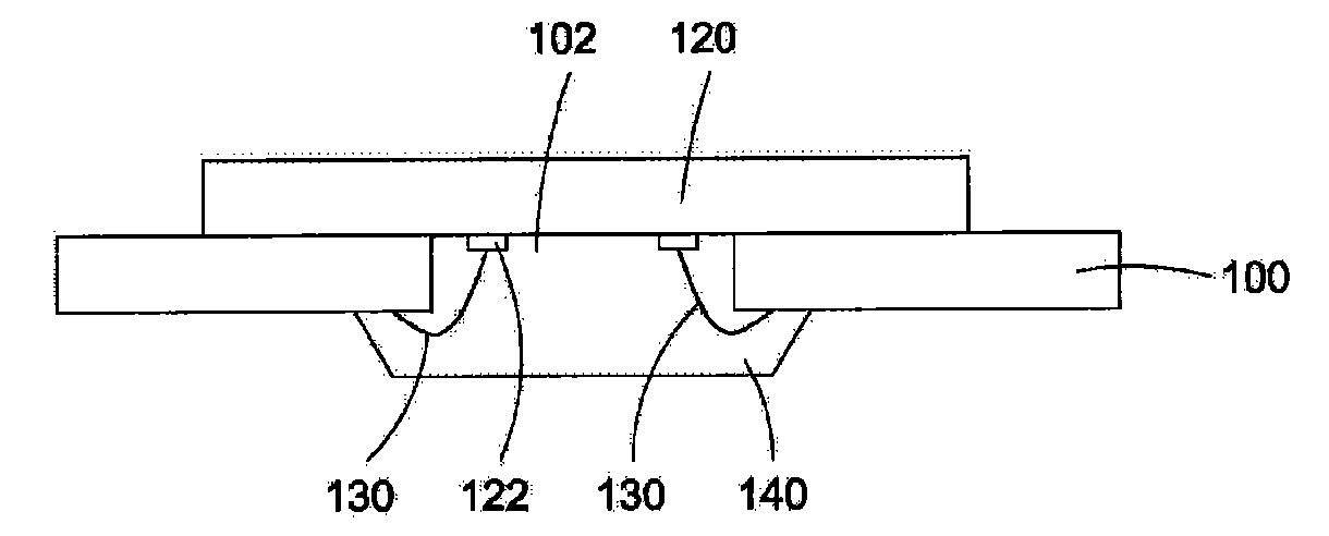
[0003] However, due to the mismatch of thermal expansion coefficient (CTE, coefficient of thermal expansion) between the package body (especially the package body formed by resin material) 140 and the chip 120 contacting the package body 140 , under the condition of high temperature , such as the curing (curing) step of the package body 140 or the subsequent thermal cycle step, especially in the part of the chip 120 due to the thermal stress (thermal stress) from the package body 140, chip cracking (chip-crack) will occur problems, and compared to longer and larger-sized chips, their reliability and yield will be reduced
In addition, during the forming process of the package body 140 , the wires of the wire bonding will contact with the resin material when the package body is formed by molding, so that there will be a problem of short circuit.

Method used


Image

  • Semiconductor packaging structure
  • Semiconductor packaging structure
  • Semiconductor packaging structure

Examples


Embodiment Construction

[0013] The direction that the present invention discusses here is a packaging structure and its packaging method, which is to provide a substrate with an opening, so that the upper and lower chips are attached to the substrate in a flip-chip manner facing the opening, and then packaged. In order to provide a thorough understanding of the present invention, detailed steps and components thereof will be set forth in the following description. Obviously, the practice of the present invention is not limited to specific details of the manner in which the chips are packaged that are familiar to those skilled in the art. For the preferred embodiments of the present invention, it will be described in detail as follows, but in addition to these detailed descriptions, the present invention can also be widely implemented in other embodiments, and the scope of the present invention is not limited, and it is described in the appended The scope defined by the claims shall prevail.

[0014]...


PUM


Abstract

The invention provides a semiconductor packaging structure, which comprises a substrate, a first chip, a first lead, a second adhesion layer, a second chip, a second lead, a first packaging body, a second packaging body and a conducting element, wherein the substrate is provided with a front and a back, and is also provided with an opening penetrating the substrate; the first chip is provided withan active surface and a back, covers the opening through a first adhesion layer in a mode that the active surface is upwards, and is attached to the back of the substrate through the first adhesion layer; the first lead is electrically connected with the first chip and the front of the substrate through the opening; the second adhesion layer coats the first lead and covers a solder pad on the active surface of the first chip and partial front of the substrate; the second chip is provided with an active surface and a back, the back of the second chip is downwards and the active surface is upwards relative to the first chip, and the second chip is attached to the front of the substrate through the second adhesion layer; the second lead is electrically connected with the active surface of the second chip and the front of the substrate; the first packaging body coats the first chip, the first adhesion layer, the first lead and partial back of the substrate; the second packaging body coststhe second chip, the second adhesion layer, the second lead and the partial front of the substrate; and the conducting element is arranged on the back of the substrate.

Description

technical field [0001] The present invention relates to a package structure and method thereof, in particular to a package structure of a substrate with openings and a method thereof. Background technique [0002] The semiconductor packaging structure with an open substrate is a more advanced packaging technology, which is characterized by: at least one opening is formed on the substrate, and allows the chip to be placed and cover the through hole of the substrate, and pass through the through hole. The wire bonded wires are electrically connected to the substrate. Such an arrangement can effectively shorten the length of wires for wire bonding, thereby forming an electrical connection between the substrate and the chip. The existing packaging structure of the substrate with openings such as figure 1 As shown, the substrate 100 has an upper surface and a lower surface and has an opening 102 passing through the substrate 100 . Next, a chip 120 is exposed to the opening 102...

Claims


Application Information

Patent Timeline
Patent Type & Authority Applications(China)
IPC IPC(8): H01L25/00H01L25/065H01L23/488H01L23/31
CPCH01L2224/16H01L2224/32225H01L2224/48091H01L2224/48227H01L2224/4824H01L2224/73215H01L2924/15311
Inventor 林鸿村吴政庭
Owner CHIPMOS TECH INC
Learn More