Chemical stripping method for optical fiber coating layer
A coating layer and optical fiber technology, which is applied in the field of chemical stripping of optical fiber coating layer, can solve the problems affecting the strength and service life of optical fiber, damage to the quartz surface of optical fiber, etc., and achieve the effect of improving surface quality, removing impurities, and enhancing strength
- Summary
- Abstract
- Description
- Claims
- Application Information
AI Technical Summary
Problems solved by technology
Method used
Image


Examples
Embodiment 1
[0021] Embodiment 1: (use chloroform and acetone to carry out soaking according to the solvent that 1:5 mixes)
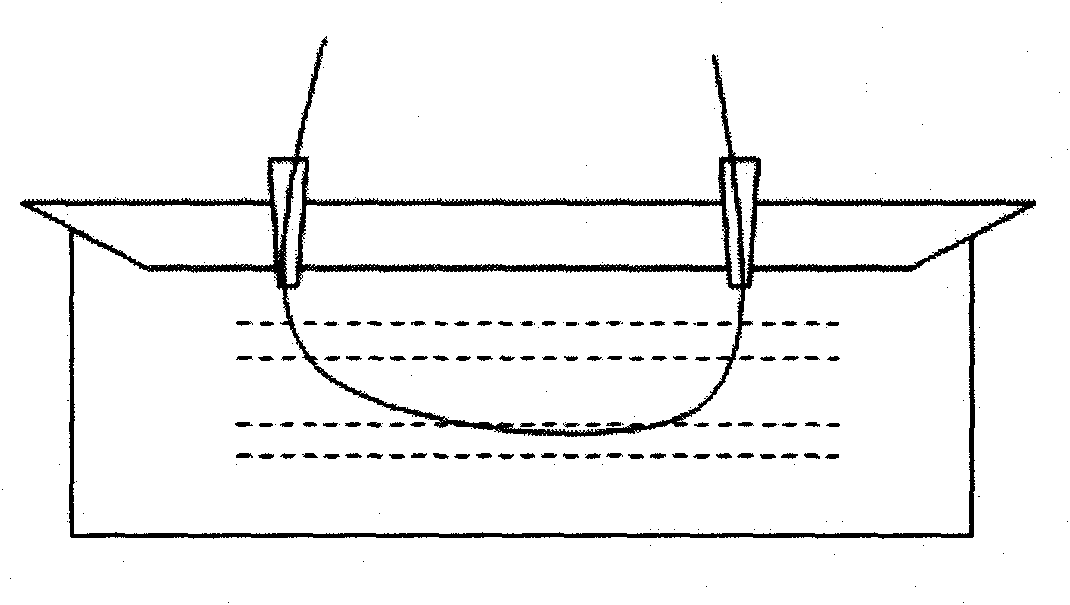
[0022] In this embodiment, chloroform and acetone are used for soaking in a solvent mixed with a molar ratio of 1:5. The soaking method is as follows: figure 1 As shown; the immersion time is 30 minutes, and the soaked optical fiber together with the rubber tube is placed in an alcohol solvent for ultrasonic oscillation, and the oscillation cleaning time is 30 minutes; the cleaned optical fiber is dried with high-purity nitrogen.
[0023] Use the static fatigue parameter test method to test the strength of the stripped optical fiber, using such as image 3 The test principle of ordinary single-mode fiber is tested, and the test result schematic diagram is as follows figure 2 shown.
Embodiment 2
[0024] Embodiment 2: (the solvent that adopts dichloromethane and methyl ethyl ketone to mix according to 1: 2 carries out immersion)
[0025] In this embodiment, the solvent mixed with dichloromethane and methyl ethyl ketone according to the soaking ratio of 1:2 is used for soaking, and the soaking method is as follows: figure 1 As shown; the immersion time is 30 minutes, and the soaked optical fiber together with the rubber tube is placed in an alcohol solvent for ultrasonic oscillation, and the oscillation cleaning time is 30 minutes; the cleaned optical fiber is dried with high-purity nitrogen.
[0026] Adopt the stripping method that similar embodiment carries out, carry out the design and manufacture of other 6 embodiments again, the stripping process and time control of the optical fiber of 1-8 embodiment are as shown in table 1, the intensity of the optical fiber after stripping The test values are shown in Table 2.
[0027] Example
Soaking Solvent Comb...
Embodiment 9
[0032] Embodiment 9: (the solvent that chloroform and octanone are mixed according to molar ratio 1: 5 is soaked)
[0033] Adopt the solvent that chloroform and octanone are mixed according to the molar ratio of 1:5 to soak, and the soaking method is as follows: figure 1 As shown; the immersion time is 30 minutes, and the soaked optical fiber together with the rubber tube is placed in an alcohol solvent for ultrasonic oscillation, and the oscillation cleaning time is 30 minutes; the cleaned optical fiber is dried with high-purity nitrogen. Other steps are the same as in Example 1. Example 10: (1,4-dichlorobutane and pentanone are soaked in a mixed solvent according to a molar ratio of 1:1)
[0034] Use 1,4-dichlorobutane and pentanone to mix the solvent according to the molar ratio of 1:1 for soaking, the soaking method is as follows figure 1 As shown; the immersion time is 90 minutes, and the soaked optical fiber together with the rubber tube is placed in an alcohol solvent...
PUM
 Abstract
Description
Claims
Application Information
 - Generate Ideas
- Intellectual Property
- Life Sciences
- Materials
- Tech Scout
- Unparalleled Data Quality
- Higher Quality Content
- 60% Fewer Hallucinations
Browse by: Latest US Patents, China's latest patents, Technical Efficacy Thesaurus, Application Domain, Technology Topic, Popular Technical Reports.
© 2025 PatSnap. All rights reserved.Legal|Privacy policy|Modern Slavery Act Transparency Statement|Sitemap|About US| Contact US: help@patsnap.com