
Edge detection device and line sensor for same

An edge detection device and a line sensor technology, applied in the field of line sensors, can solve the problem that it is difficult to correctly judge the detection, change of the edge part, and the increase in the degree of change of the light-receiving signal.

Inactive Publication Date: 2010-02-03
YAMATAKE HONEYWELL CO LTD
View PDF1 Cites 3 Cited by
  • Summary
  • Abstract
  • Description
  • Claims
  • Application Information

AI Technical Summary

Problems solved by technology

However, when the shield 104 is a transparent body such as glass or a thin film, since the laser monochromatic light passes through the shield 104, compared with the case where the shield 104 is an opaque shield 104, the edge portion very difficult to detect
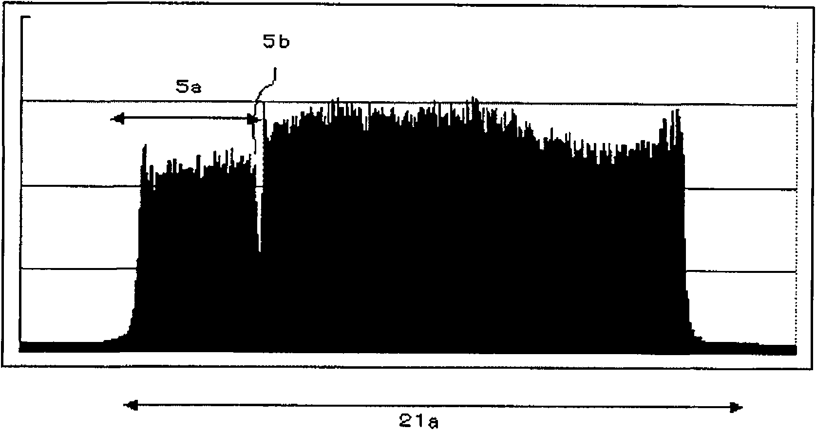
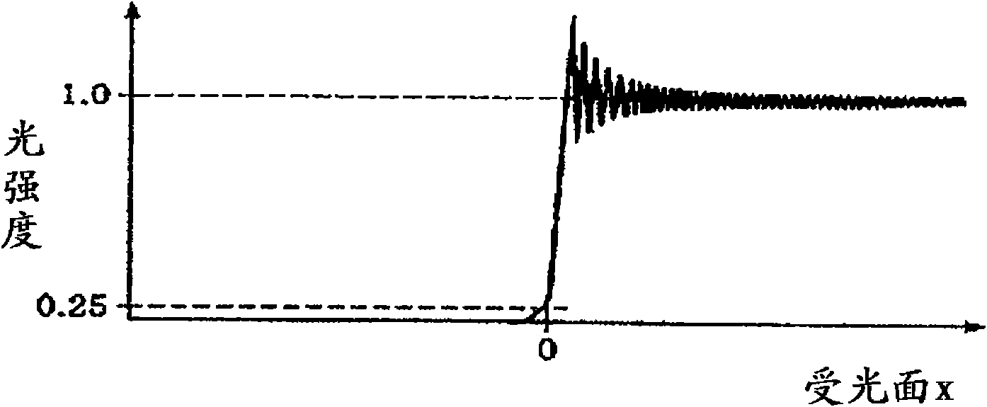
In particular, depending on the insertion status (insertion position) of the shield 104 of a transparent body, by using Fresnel diffraction generated at the edge of the shield 104, the amount of received light may attenuate even for a transparent body, but the attenuation depends on the The position of the occluder 104 is reduced, making it difficult to judge the edge
For example, there is a case where if a transparent film as the shield 104 is inserted vertically with respect to the monochromatic laser light, the attenuation of the received light amount is large and the edge portion can be detected, but when inserted in an oblique state, the attenuation of the received light amount Small, edge parts cannot be detected correctly
As an edge detection device, there are cases where there is meandering detection when a thin film is rolled up. Since the insertion direction of the film is not fixed at this time, the attenuation of the received light is small and unstable, and it is difficult to accurately judge the edge portion. detection
[0007] In addition, the light source 101a also has the following problem: Since the emission wavelength of the output laser monochromatic light varies with the ambient temperature, the interference pattern of the irradiated laser monochromatic light changes depending on the temperature, and the light emitted to the line sensor 100 The pattern of parallel light changes
[0009] In this way, the conventional edge detection device has the problem that the wavelength or output power of the monochromatic laser light changes with the change of the ambient temperature, and the light receiving signal output by each light receiving unit fluctuates, which adversely affects the performance of the device, and it is difficult to perform accurate edge detection.
In particular, since the attenuation of received light due to Fresnel diffraction at the edge is small due to a transparent body such as a film, it is difficult to detect the edge in an unstable distribution of received light.
In addition, due to the diffuse reflection or new interference of the monochromatic laser light incident on the cover glass of the line sensor, the degree of fluctuation of the light receiving signal output by each light receiving unit increases, so it cannot be used for high-precision edge detection. cheap wire sensor

Method used


Image

  • Edge detection device and line sensor for same
  • Edge detection device and line sensor for same
  • Edge detection device and line sensor for same

Examples


Embodiment Construction

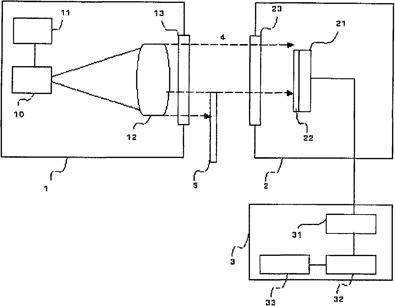
[0030] figure 1 It is a figure which shows the structure of the edge detection apparatus which concerns on embodiment of this invention. exist figure 1 In this embodiment, the edge detection device includes a light projector light emitting unit 1 , a light receiver light receiving unit 2 , and an edge detection unit 3 . The light projecting part 1 of the light emitter is disposed opposite to the light receiving surface of the light receiving window 23 of the light receiving part 2 of the light receiver, and has a light source 10 composed of a laser diode (LD), a driver IC 11 for controlling the light source 10, a light projecting lens 12 and a light projecting lens 12. window 13. The light projecting lens 12 emits and outputs the monochromatic light generated by the light source 10 to the middle part of the line sensor 21 of the light receiver 2 through the light projecting window 13 . Here, the monochromatic light refers to light having a wavelength distribution characte...


PUM


Abstract

The invention provides an edge detection device. Even if a measuring medium is a thin transparent body like a film, the edge detection device is not influenced by the insertion condition, and under the condition that the ambient temperature in a measurement space changes, the edge detection device can correctly detect edge parts, and can easily avoid edge error detections of a sheltering object inspite of the manufacturing deviation of each formed component. The edge detection device is provided with the following components: a light projector which consists of a laser source, a light projection lens and a light projection window; a light receiving window for receiving monochromatic parallel light; a light sensor which is provided with a plurality of light receiving units in the length direction; a light path changing part which changes the monochromatic parallel light inbreaking from the light receiving window to a plurality of light paths corresponding to the vertical direction of alight receiving element; and a detection part which detects the edge position of the sheltering object according to the light intensity distribution of the line sensor caused by the Fresnel diffraction of the monochromatic parallel light of the edge parts of the sheltering object existing on the light paths of a light projection window and the light receiving window and generated by the light path changing part.

Description

technical field [0001] The present invention relates to an optical edge detection device for receiving a monochromatic parallel light beam emitted from a light projector by a light receiver, and detecting the edge position of an object blocking the monochromatic parallel light beam, and a technology of a line sensor used in the edge detection device. Background technique [0002] Figure 9 It is a figure which shows the structure of the conventional edge detection apparatus disclosed by patent document 1. exist Figure 9 Among them, the edge detection device has a line sensor 100 , a light projector 101 , and an edge detection unit 102 . The line sensor 100 has a plurality of light receiving units (pixels) arranged at a predetermined pitch in a certain direction, and receives monochromatic parallel light emitted from the light projector 101 . The light projector 101 is arranged so as to face the light-receiving surface of the line sensor 100, and has a light source 101a com...

Claims


Application Information

Patent Timeline
Patent Type & Authority Applications(China)
IPC IPC(8): G01B11/00
Inventor 越俊树加纳史朗
Owner YAMATAKE HONEYWELL CO LTD
Learn More