Device and method for detecting transmittance of thin film polarizer

A thin-film polarizer and detection device technology, which is applied in the laser field, can solve the problems that the transmittance of thin-film polarizers cannot be accurately tested, and achieve the effects of improving measurement accuracy, avoiding measurement errors, and accurate test results

Pending Publication Date: 2022-05-20
HARBIN INST OF TECH
View PDF0 Cites 2 Cited by
  • Summary
  • Abstract
  • Description
  • Claims
  • Application Information

AI Technical Summary

Problems solved by technology

[0004] The first purpose of the present invention is to provide a detection device for the transmittance of the film polarizer in order to solve the problem that the transmittance of the film polarizer cannot be accurately tested in the prior art

Method used


Image

  • Device and method for detecting transmittance of thin film polarizer

Examples


specific Embodiment approach 1

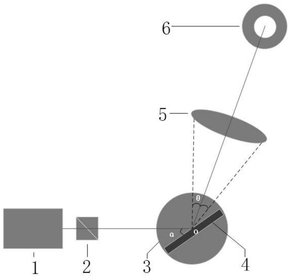
[0029] A detection device for the transmittance of a thin-film polarizer, comprising a test light source 1, a polarization cube 2, a rotary table 3, a mounting base 4, a convex lens 5 and a power meter 6, the mounting base 4 is fixedly arranged on the rotary table 3 and two The center of the film polarizer to be tested is set on the mount 4 and the centers of the two are coincident. The light emitted by the test light source 1 passes through the polarization cube 2, is incident on the film polarizer to be tested, and is reflected by the film polarizer to be tested. To the center of the convex lens 5, and then reach the power meter 6, the angle α between the light emitted by the test light source 1 and the plane where the film polarizer to be tested is located is 33 ± 1 °, and the focal length of the convex lens 5 is f, so The distance between the center of the convex lens 5 and the center of the turntable 3 and the distance between the center of the convex lens 5 and the power ...

specific Embodiment approach 2

[0034] A method for detecting the transmittance of a thin film polarizer using the detection device described in Embodiment 1, comprising the following steps:

[0035] Step 1, fixing the mounting base 4 at the rotation center point O of the rotary table 3, and then setting the film polarizer to be measured at the center of the mounting base 4;

[0036] Step 2. Place the test light source 1 and turn it on, so that the light emitted by it is incident on the center of the film polarizer to be tested, and the rotating table 3 is turned so that the light emitted by the test light source 1 is between the plane of the film polarizer to be tested. The included angle α is 33±1°;

[0037] Step 3, place the polarizing cube 2 and the convex lens 5, so that the light emitted by the test light source 1 passes through the center of the polarizing cube 2, the film polarizer to be tested, and the convex lens 5 in sequence;

[0038] Step 4, adjust the position of the convex lens 5 so that the ...


PUM

PropertyMeasurementUnit
Clear apertureaaaaaaaaaa

Abstract

A device for detecting the transmittance of a thin film polarizer belongs to the technical field of laser, and comprises a test light source, a polarization cube, a rotary table, a mounting seat, a convex lens and a power meter, the mounting seat is fixedly arranged on the rotary table, and the centers of the mounting seat and the rotary table are overlapped; a to-be-tested film polaroid is arranged on the mounting seat, the centers of the to-be-tested film polaroid and the mounting seat coincide, and light emitted by the test light source penetrates through the polarization cube, enters the center of the to-be-tested film polaroid, is reflected to the center of the convex lens through the to-be-tested film polaroid and then reaches the power meter. The distance between the center of the convex lens and the center of the rotary table and the distance between the center of the convex lens and the power meter are both 2f. The detection device can ensure that the reflected light always stably enters the center of the probe of the power meter when the thin film polaroid is rotated near the Brewster angle, so that test errors caused by repeated movement of the position of the power meter in the test process are avoided, and the measurement accuracy is further ensured.

Description

technical field [0001] The invention belongs to the field of laser technology, and in particular relates to a detection device and method for the transmittance of a thin film polarizer. Background technique [0002] Thin-film polarizer is a kind of optical polarizer, which uses the interference effect of multilayer dielectric film to obtain polarized light. When the optical film is coated on glass and other materials, the film polarizer will allow s-polarized light to reflect and p-polarized light to transmit when it is incident at certain angles. Usually the incident angle is designed to be Brewster's angle, which can avoid the reflection loss of the back transmitted light. Thin-film polarizers are commonly used optical components in Q-switched Nd:YAG lasers, and their transmittance to p-polarized light is an important parameter that needs to be considered when designing Q-switched lasers. Therefore, the p-light transmittance of thin-film polarizers can be accurately obtai...

Claims


Application Information

Patent Timeline
IPC IPC(8): G01N21/59G01M11/02
CPCG01N21/59G01M11/02
Inventor 李旭东陈兆东闫仁鹏董志伟樊荣伟陈德应
Owner HARBIN INST OF TECH
Why Eureka
Try Eureka