
Automatic spiral hole-milling unit

A helical milling and automatic technology, which is applied to milling machine equipment, milling machine equipment details, metal processing equipment, etc., can solve the problem that manual tools cannot provide usability solutions, cannot meet the requirements of hole processing quality, and affect coaxiality and surface quality and other issues to achieve the effect of shortening the development cycle, shortening the research and development cycle, and reducing the cost of the enterprise

Inactive Publication Date: 2010-01-27
TIANJIN UNIV
View PDF0 Cites 39 Cited by
  • Summary
  • Abstract
  • Description
  • Claims
  • Application Information

AI Technical Summary

Problems solved by technology

The hand tool disclosed in this patent does not provide a practical usability solution and it is far from meeting the requirements for hole machining quality in the aerospace field
Because its obvious disadvantages are: positioning is manual, which seriously affects the position accuracy of the hole, and hand-held, cannot provide too much rigidity, which will also affect the coaxiality and surface quality of the hole
A basic requirement for such a hand tool is light weight and ease of use, and this patent does not provide a compact and lightweight structure

Method used


Image

  • Automatic spiral hole-milling unit
  • Automatic spiral hole-milling unit
  • Automatic spiral hole-milling unit

Examples


Embodiment Construction

[0019] The present invention will be described in detail below in conjunction with the accompanying drawings and specific embodiments.

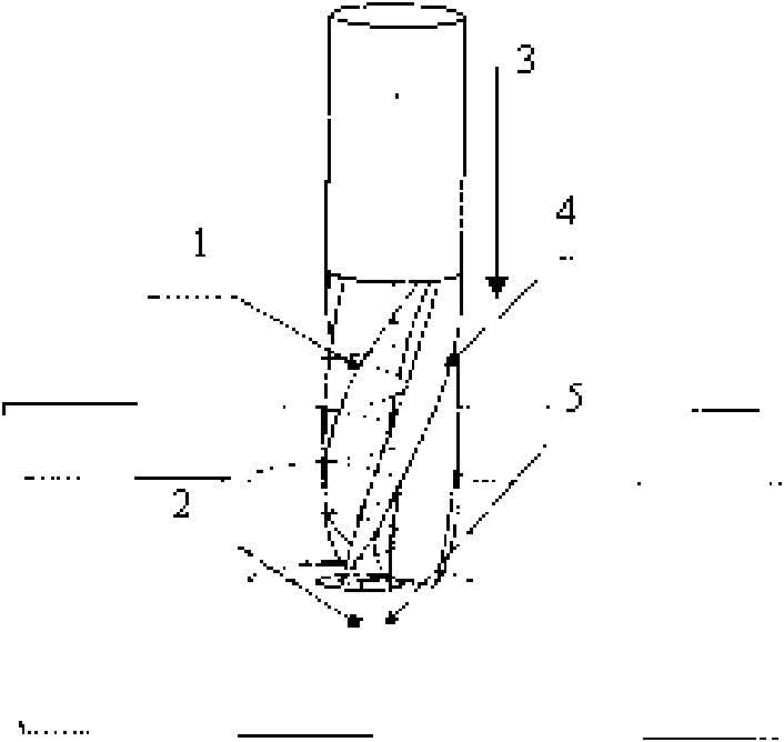
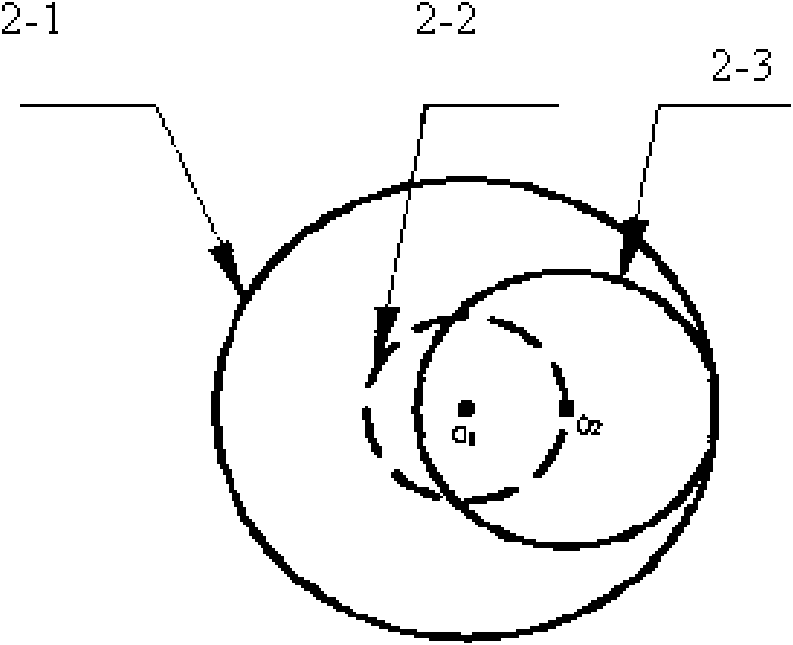
[0020] like Figure 1-2 As shown, the structure of the present invention is developed based on a helical milling process. Thus, the principle of helical milling is the essence of the present invention. like figure 1 As shown, where 1 refers to the movement track of the tool center, 2 refers to the centerline of the hole, 3 refers to the axial feed direction, 4 refers to the tool, and 5 refers to the centerline of the tool. The helical milling process is a "milling instead of drilling" process, which uses helical feed to realize cutting motion. The movement of the helical milling process is composed of the "autorotation" movement of the spindle, the "revolution" movement of the tool around the centerline of the hole, and the Z-direction feed of the spindle. These three movements are compounded. This special movement mode determines Advanta...


PUM


Abstract

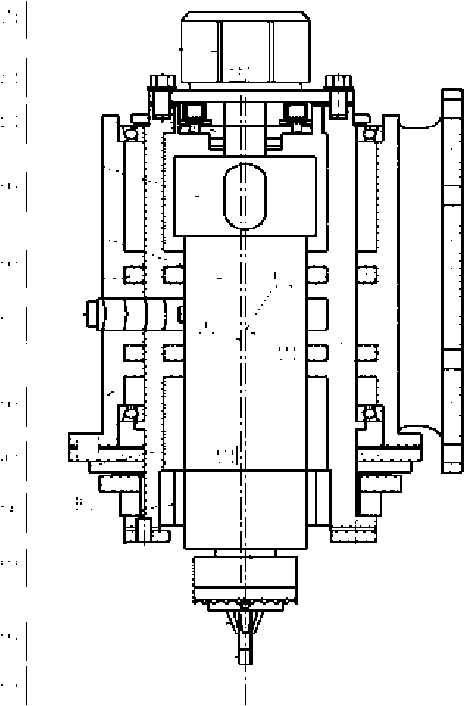
The invention discloses an automatic spiral hole-milling unit comprising a cutter rotation system, a radial deflection system, a revolution system and a sleeve with an inner hole. The axis of the inner hole of the sleeve is eccentrically arranged relative to the axis of an outer circumference of the sleeve. A stand is connected outside the sleeve. The cutter rotation system comprises a drive unit with a cylindrical shell. The drive unit can be rotatably arranged inside the inner hole of the sleeve. An output shaft of the drive unit is connected with a clamping apparatus holding a cutter. The output shaft of the drive unit is in offset arrangement relative to the axis of the shell of the drive unit. The radial deflection system comprises a stepping motor with an electromagnetic brake. A flange of the stepping motor is fixedly connected with the sleeve, and an output shaft of the stepping motor is fixedly connected with the shell of the drive unit coaxially. The revolution system comprises an electric rotating motor; the inner ring of the electric rotating motor is fixedly connected on the sleeve, and the outer ring of the electric rotating motor is fixed on the frame. When used for processing of high-strength materials difficult to cut and process, the automatic spiral hole-milling unit obviously improves the processing efficiency and the processing quality.

Description

technical field [0001] The invention relates to an automatic drilling and riveting equipment which is a necessary equipment in the assembly process of a large aircraft, in particular to an automatic helical milling hole unit. Background technique [0002] Now our country is in a period of rapid development of manufacturing technology, and cutting processing is the main basic process of manufacturing technology. Aerospace is one of the most important components of the manufacturing industry and the industry with the most high-tech enrichment. In aerospace manufacturing, a large number of components need to be assembled, and thousands of holes need to be machined. Modern aircraft assembly puts forward new requirements for automatic hole making. Due to the requirements of long service life, stealth, and structural interchangeability of modern aircraft structures, more precise and stricter assembly holes are required; secondly, the proportion of difficult-to-machine materials ...

Claims


Application Information

Patent Timeline
IPC IPC(8): B23C3/00
Inventor 秦旭达滑松冀晓来王琦
Owner TIANJIN UNIV
Learn More