
Accelerator used for cancer therapy with protons-heavy ion beams

A heavy ion beam and accelerator technology, which is applied in the field of proton-heavy ion beam cancer treatment devices, can solve the problems of complex requirements for magnets and magnet power supplies, large linear accelerators, and rising investment costs, achieving small footprint, easy maintenance and The effect of low repair and construction costs

Active Publication Date: 2010-01-20
INST OF MODERN PHYSICS CHINESE ACADEMY OF SCI
View PDF3 Cites 16 Cited by
  • Summary
  • Abstract
  • Description
  • Claims
  • Application Information

AI Technical Summary

Problems solved by technology

During a linac operating cycle, ions are extracted for only a small fraction of the total cycle, resulting in increased injection time
At the same time, the linear accelerator has a large volume, high cost, and complex requirements for magnets and magnet power supplies, which increases the cost of construction and investment
[0007] Another defect of this known heavy ion cancer treatment device is that although the adoption of the six-fold synchrotron ring has reduced the volume of the heavy ion cancer treatment device to a certain extent, it has caused the reduction of the linear section of the synchrotron at the same time. It is impossible to install a cooling device for repeated injection and beam accumulation, so it is necessary to achieve the clinically required beam intensity in one injection. This defect increases the performance requirements of the ion source and linear accelerator of this device, resulting in investment costs rise
[0008] In addition, in the known accelerator devices for proton and heavy ion cancer treatment, the ion implantation provided by the linear accelerator into the synchrotron adopts a multi-circle implantation method, which has the disadvantage of low efficiency of a single injection, which in turn increases the treatment time

Method used


Image

  • Accelerator used for cancer therapy with protons-heavy ion beams
  • Accelerator used for cancer therapy with protons-heavy ion beams
  • Accelerator used for cancer therapy with protons-heavy ion beams

Examples


Embodiment Construction

[0025] Below in conjunction with the preferred embodiment shown in accompanying drawing, be described in further detail:

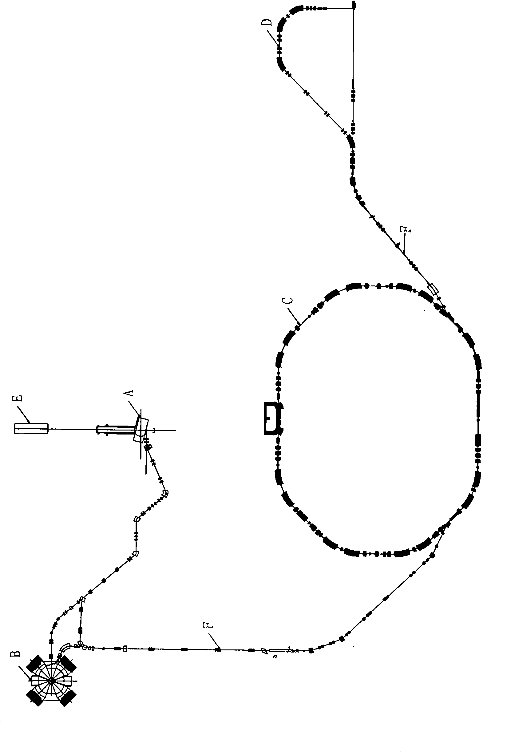
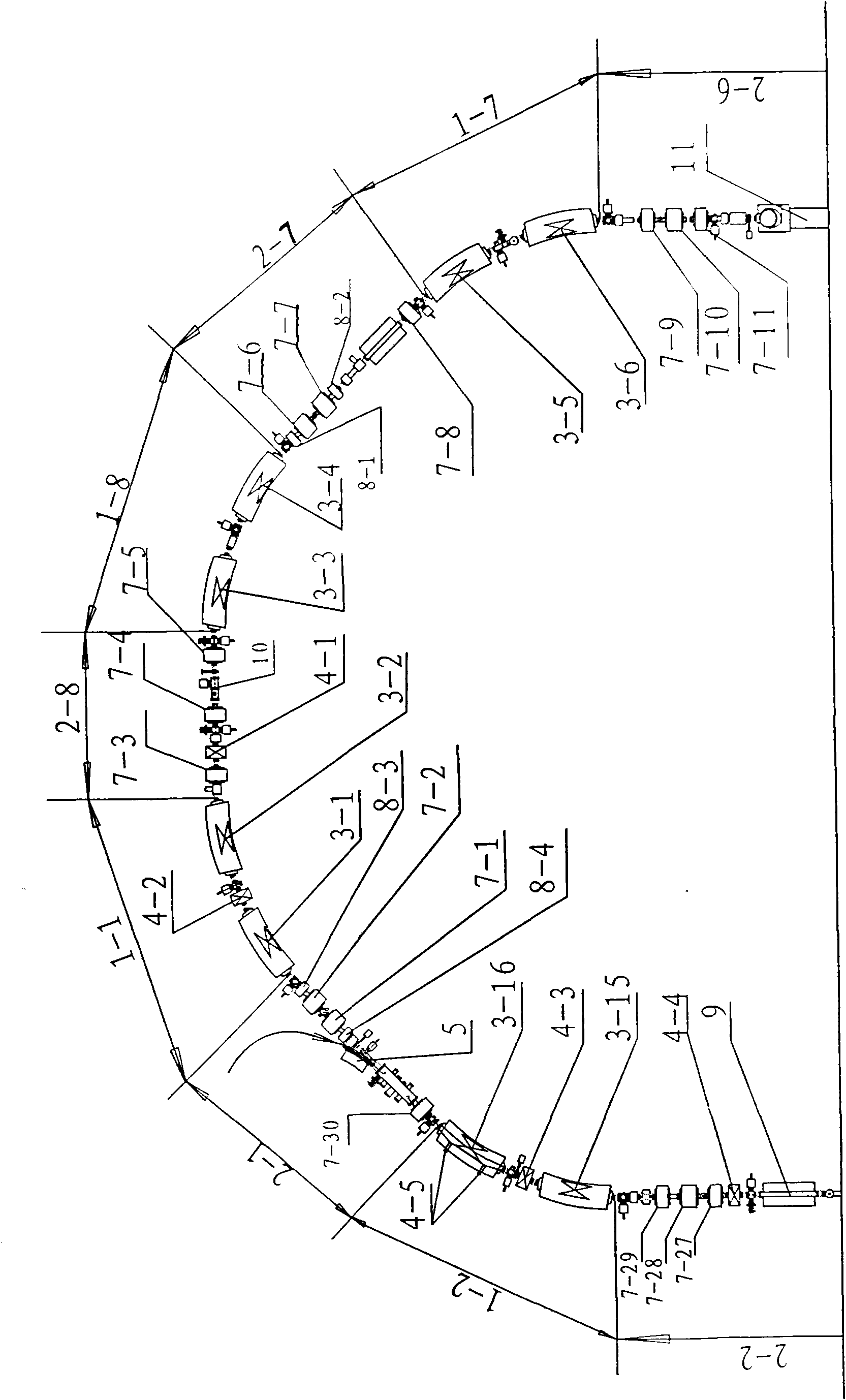
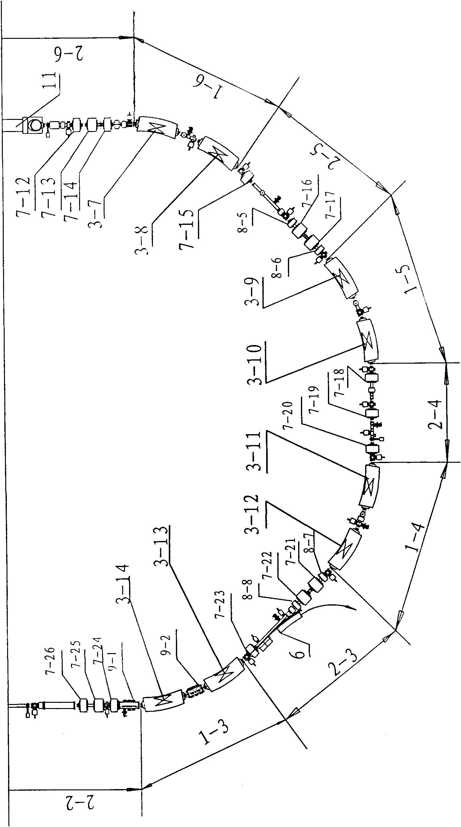
[0026] See figure 1 , 2 3. The accelerator for treating cancer with proton-heavy ion beams includes an ion source E and a synchrotron C, which is characterized in that: a fan focusing cyclotron A or / or is provided at the ion beam injection end of the synchrotron C and separate fan-focusing cyclotron B. The synchrotron C includes an injection cutting magnet device 5, an extraction cutting magnet device 6, a high-frequency accelerating device 9, eight synchrotron bending sections 1-1 to 1-8 and eight synchrotron linear sections 2-1 to 2-8.

[0027]The synchrotron bending section 1-1 includes two dipole magnets 3-1, 3-2; the synchrotron bending section 1-2 includes two dipole magnets 3-15, 3-16; the synchrotron bending Section 1-3 includes two dipole magnets 3-13, 3-14 and electrostatic deflection plate 9-2; synchrotron bending section 1-4 includes two di...


PUM


Abstract

The invention relates to an accelerator which combines a cyclotron and a synchrotron and is used for cancer therapy with protons-heavy ion beams, comprising an ion source E and the synchrotron C. The accelerator is characterized in that the synchrotron C comprises a septum magnet implanting device (5), a septum magnet extracting device (6), a radio-frequency accelerating device (9), eight bending sections of the synchrotron (1-1 to 1-8) and eight straight sections of the synchrotron (2-1 to 2-8), which are connected by an ion beam transmission line F; the ion beam implantation end of the synchrotron C is provided with a sector focusing cyclotron A or / and a separated sector focusing cyclotron B. By adopting the method of combining the cyclotron and the synchrotron, a set of accelerator devices required by cancer therapy with protons and heavy ion beams is set up to realize the requirements of clinical therapy on beam parameters; the mass numbers of the protons and the heavy ions are less than or equal to 40; the protons and heavy ion beams have wide energy range from 10MeV / u to 400MeV / u and high flux (the ion number provided by each pulse is up to 10<7-10> magnitude).

Description

Technical field: [0001] The invention relates to the technical field of a proton-heavy ion beam cancer treatment device combining a cyclotron and a synchrotron, in particular to an accelerator for proton-heavy ion beam cancer treatment. Background technique: [0002] Proton-heavy ion Beam cancer treatment has become an advanced and effective cancer radiotherapy method in the world today. At present, the results of preliminary clinical treatment trials show that proton-heavy ion beam therapy has a very significant curative effect on cancer, and there is no obvious side effect. [0003] In the implementation of proton-heavy ion beam irradiation therapy, an accelerator that provides a beam that meets clinical requirements is the most basic device. According to the depth of different tumors in clinical treatment, the accelerator needs to provide ion beams with different energies; according to the shape of different tumors, the accelerator needs to be able to precisely control ...

Claims


Application Information

Patent Timeline
IPC IPC(8): H05H13/04A61N5/00
Inventor 夏佳文原有进宋明涛杨建成
Owner INST OF MODERN PHYSICS CHINESE ACADEMY OF SCI
Learn More