Realizing method of driving signal

A technology for driving signals and implementation methods, applied in the direction of pulse technology, single pulse train generator, pulse processing, etc., can solve the problems of inability to drive signals to drive electronic equipment, and achieve the effect of reducing performance requirements and reducing costs

Inactive Publication Date: 2010-01-13
AAC TECH PTE LTD +1
View PDF0 Cites 3 Cited by
  • Summary
  • Abstract
  • Description
  • Claims
  • Application Information

AI Technical Summary

Problems solved by technology

[0002] The existing signal generator can only realize the generation of a single cycle signal, so the signal generator can only be used as a single cycle signal source, and cannot be used as a driving signal to directly drive electronic equipment

Method used


Image

  • Realizing method of driving signal
  • Realizing method of driving signal
  • Realizing method of driving signal

Examples


Embodiment Construction

[0032] The specific structure of the present invention will be described in detail below in conjunction with the accompanying drawings.

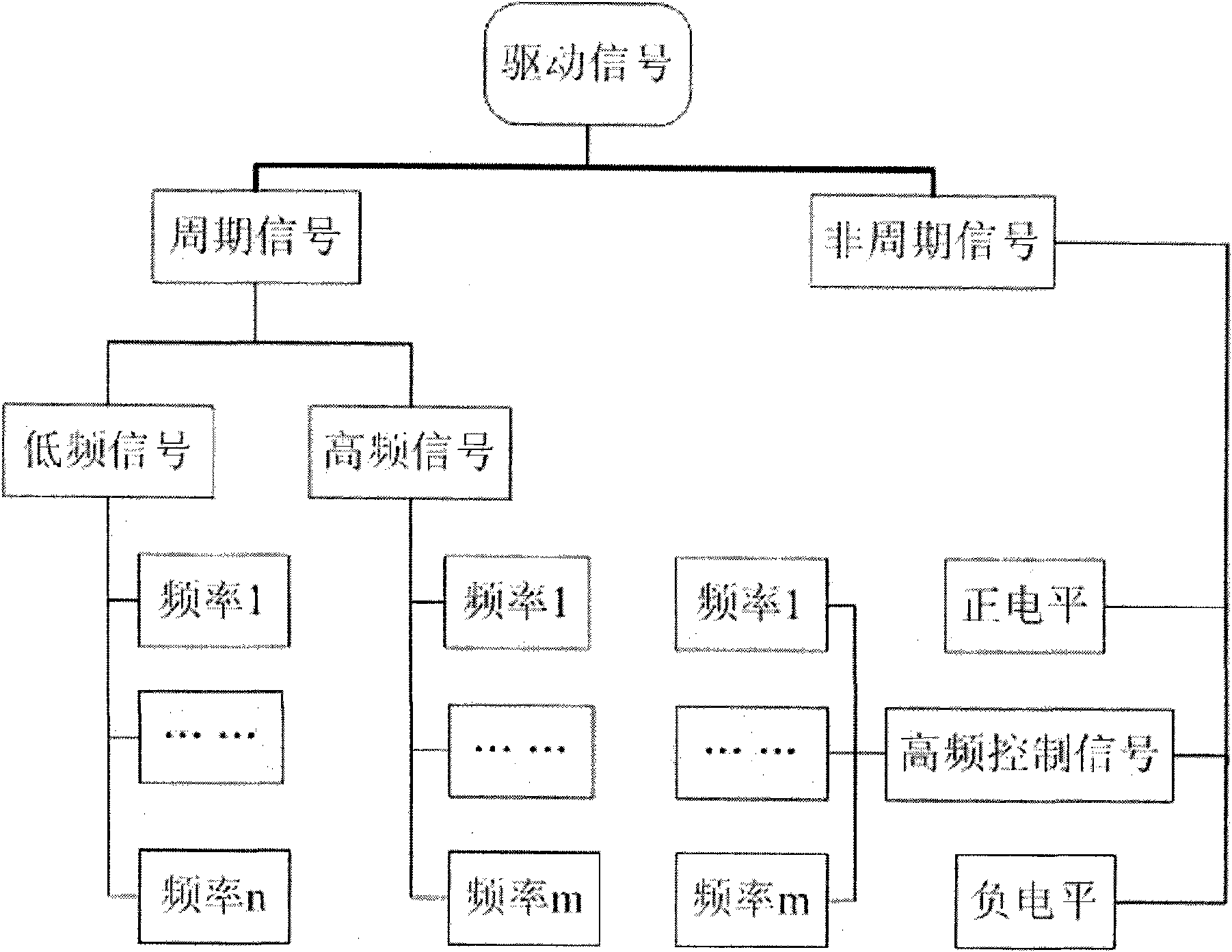
[0033] A device for generating driving signals, which includes at least one low-frequency generator, at least one high-frequency generator, a logic circuit module connected to the low-frequency generator and the high-frequency generator respectively, a calculation module connected to the logic circuit module, and a calculation module connected with the calculation module. The module is connected to the H-bridge circuit module.

[0034] The driving signal realized by the present invention needs strict timing control, so the low-frequency signal generator is required to have timing and counting functions, such as PLC, single-chip microcomputer, DSP, FPGA and PC, etc., according to specific accuracy and cost requirements, one of them can be selected arbitrarily or several.

[0035] The high-frequency signal generator can adopt various oscillat...


PUM


Abstract

The invention relates to a realizing method of a driving signal. Devices involved in the method comprise a low-frequency signal generator, a high-frequency signal generator, an H-bridge circuit and a logic circuit. The driving signal obtained by the method can realize complex driving signals of non-single period and level to directly drive electronic devices.

Description

【Technical field】 [0001] The invention relates to a method for realizing a signal, in particular to a method for realizing a driving signal. 【Background technique】 [0002] Existing signal generators can only realize the generation of single-period signals. In this way, the signal generator can only be used as a single-period signal source, and cannot be used as a driving signal to directly drive electronic equipment. [0003] Therefore, it is necessary to provide a driving signal implementation method to overcome the above-mentioned defects. 【Content of invention】 [0004] The technical problem to be solved by the present invention is to provide a method for realizing a driving signal that can directly drive an electronic device. [0005] The present invention solves above-mentioned technical problem by such technical scheme: [0006] A device for generating a driving signal, the device includes at least one low-frequency generator, at least one high-frequency generator...

Claims


Application Information

Patent Timeline
Patent Type & Authority Applications(China)
IPC IPC(8): H03K3/78H03K5/00
Inventor 张丽宏徐斌
Owner AAC TECH PTE LTD
Why Eureka
Try Eureka